Queuing closed loop congestion mechanism

a closed loop and congestion mechanism technology, applied in the field of telecommunications and packet networks, can solve the problems of increasing the ineffective bandwidth when compared to data or packet networks, and further complicated congestion of packet networks, and achieves the effects of low delay and delay variation, easy implementation and simple algorithms

Inactive Publication Date: 2008-04-22
VERIZON PATENT & LICENSING INC
View PDF8 Cites 10 Cited by
  • Summary
  • Abstract
  • Description
  • Claims
  • Application Information

AI Technical Summary

Benefits of technology

[0017]Yet another technical advantage of the present invention includes the capability to use inputs derived from a first queue of a packet switch to enable or enforce policy decisions at one or more other queues.
[0018]The present invention provides the significant technical advantage that includes the capability to provide a scalable solution that may be implemented at one or more egress ports of one or more packet switches of a packet network without any bandwidth or connection limitations.
[0019]Yet another technical advantage of the present invention concerns the capability to provide congestion management to virtually any packet switch technology or protocol, including those that utilize fixed or variable length packets or cells.
[0020]Another technical advantage of the present invention includes the capability to e

Problems solved by technology

Traditionally, voice communications or voice telephony was provided over traditional circuit-dedicated or circuit-switched telecommunications networks, which are bandwidth inefficient when compared to data or packet networks (hereinafter “packet networks”).
Unfortunately, the increased demand for the use of packet networks to exchange real-time information has resulted in increased congestion of such packet networks.
Congestion of packet networks is further complicated by the need to provide different levels or classes of services for the exchange of voice and video over packet networks.
Unfortunately, since not all packet network technology was originally designed to support the real-time exchange of voice and/or video information, the capability to implement the different levels or classes of services, while also providing a solution to the congestion problem mentioned above, is considerably challenging.
Thus, the delay or delay variation for the transmi

Method used


Image

  • Queuing closed loop congestion mechanism
  • Queuing closed loop congestion mechanism
  • Queuing closed loop congestion mechanism

Examples


Embodiment Construction

[0029]It should be understood at the outset that although an exemplary implementation of the present invention is illustrated below, the present invention may be implemented using any number of techniques, whether currently known or in existence. The present invention should in no way be limited to the exemplary implementations, drawings, and techniques illustrated below, including the exemplary design and implementation illustrated and described herein.

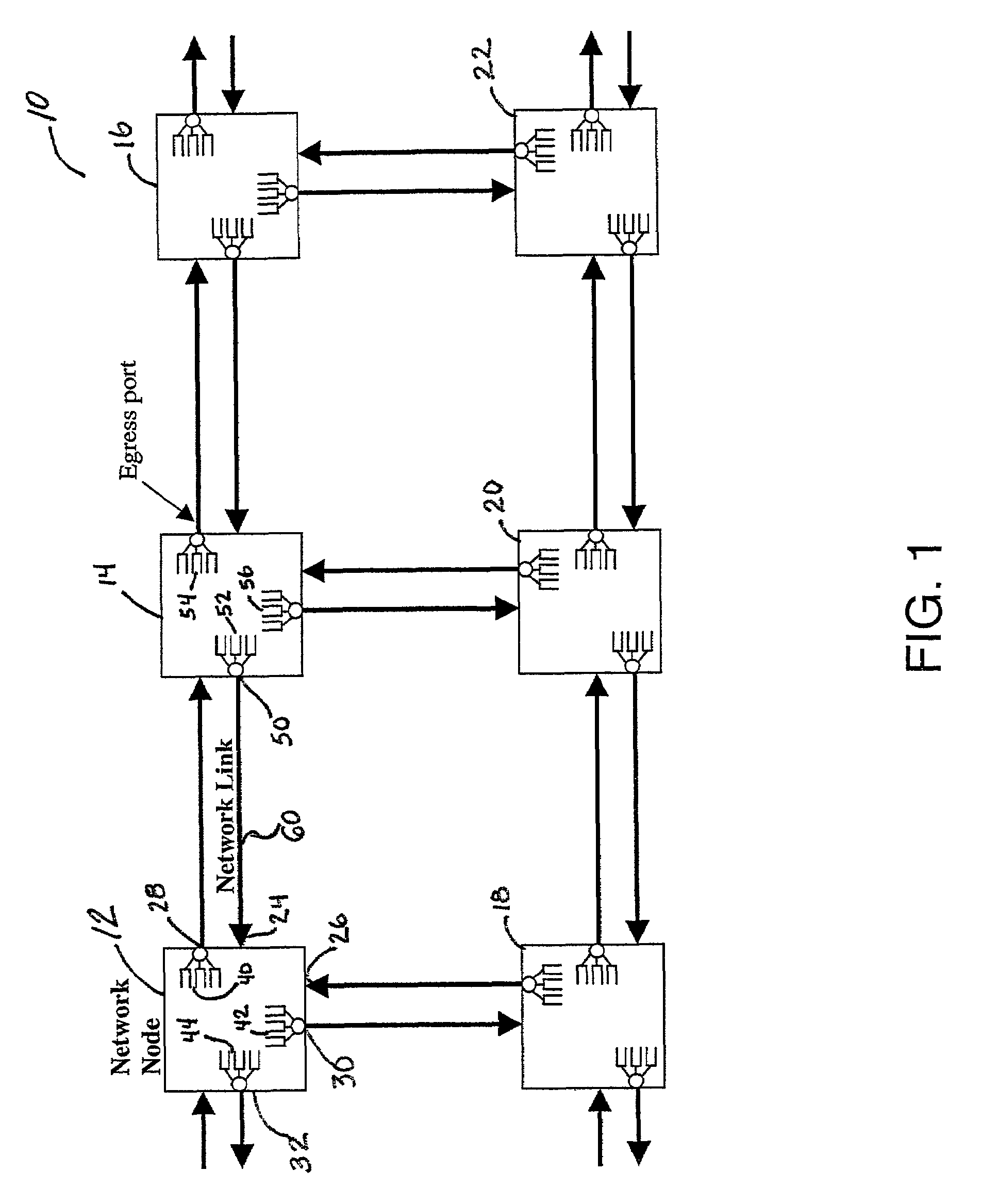
[0030]FIG. 1 is a block diagram that illustrates a packet network 10 that includes various packet switches with queuing closed loop congestion mechanisms to provide congestion management at the egress ports of the various packet switches. The packet network 10 includes a packet switch 12, a packet switch 14, a packet switch 16, a packet switch 18, a packet switch 20, and a packet switch 22. Each of these packet switches are in communication with adjoining packet switches through the various telecommunications links shown in FIG. 1 wi...


PUM


Abstract

An exemplary queuing congestion mechanism and method are disclosed that provide congestion management at an egress port of a packet switch. The queuing congestion mechanism includes at least a first, a second and a third queue, which each have an input, an output, and a capacity. Each queue is operable to receive packets of information of a designated type, such as a service category type, at its input that are destined to be communicated to the egress port through its output. The queuing congestion mechanism further includes a scheduler and a queue shaper. The scheduler, which may be implemented as a strict scheduler, is operable to receive the packets of information from the output of the queues and to communicate the packets of information to the egress port of the packet switch based on a schedule. The queue shaper is operable to set an adjustable rate in which the packets of information of the third queue are communicated to the scheduler, and the adjustable rate is controlled by a loading of the capacity of the second queue. The queuing congestion mechanism may include a discard policy that is enabled for one or more of the queues and that is based on the loading of the capacity of one of the other queues.

Description

TECHNICAL FIELD OF THE INVENTION[0001]This invention relates in general to the field of telecommunications and packet networks and more particularly to a queuing congestion mechanism, such as a queuing closed loop congestion mechanism, for use in managing and reducing congestion in packet or data networks and / or packet switches.BACKGROUND OF THE INVENTION[0002]The need for both voice telephony services as well as data services is common. Traditionally, voice communications or voice telephony was provided over traditional circuit-dedicated or circuit-switched telecommunications networks, which are bandwidth inefficient when compared to data or packet networks (hereinafter “packet networks”). For a variety of reasons, including reduced overall costs, increased efficiency, and the popularity of the Internet and other packet networks, the demand for exchanging real-time or near real-time information, such as voice and video, over such packet networks has dramatically increased.[0003]Unf...

Claims


Application Information

Patent Timeline
IPC IPC(8): H04L12/50H04L12/56
CPCH04L47/10H04L47/12H04L47/22H04L47/2441H04L47/263H04L47/30H04L47/32H04L2012/5671H04L2012/5679
Inventor BISHARD, CLINT J.
Owner VERIZON PATENT & LICENSING INC
Why Eureka
Try Eureka