Manually operated moistener for items with a water-activated glue

a technology of water-activated glue and moistener, which is applied in the direction of addressing machines, printing, writing accessories, etc., can solve the problems of affecting the cleaning cycle, affecting the actuation of the letter closer of the efs and ultimail® franking machines commercially available from francotyp, and affecting the maintenance of the moistener. , to achieve the effect of improving the maintenance, facilitating the cleaning of such a manual moistener, and

Inactive Publication Date: 2008-06-10
FRANCOTYP POSTALIA
View PDF15 Cites 4 Cited by
  • Summary
  • Abstract
  • Description
  • Claims
  • Application Information

AI Technical Summary

Benefits of technology

[0016]An object of the present invention is to provide a manual moistener that is improved with regard to maintenance. A further object is to provide such a manual moistener water fill opening that is covered nut which is easily accessible in an uncomplicated manner while still achieving low evaporation. Another object is to make cleaning of such a manual moistener easier, wherein water spillage is prevented upon loosening the connection of the water reservoir from its normal position. A further object is to design a water transfer and moistening arrangement for such a manual moistener that requires less maintenance and has an easier wetting capability, and that is easily exchangeable and has a sufficient water dispensing quantity to moisten even large, transversally-lying envelope flaps.
[0017]The invention is based on the recognition that maintenance of the moistener assembly by an operator is more easily possible when it can be exclusively, effectively undertaken from above. This is accomplished by the moistener rocker being accessible from above and being spring-mounted such that it can rotate on an associated hinge on the blade and can be locked in a maintenance position by a locking contour.
[0018]The above objects also are achieved by the upper part and lower part of the moistener being connected by fastening with connection elements that can be detached exclusively from above. Accidental spilling of the residual water thus is prevented during a regular cleaning interval. The above objects are also achieved by an antibacterial lower water transfer element in the lower part and an antibacterial upper moistening elements in the upper part which, by bending the upper end of the lower water transfer element, have an enlarged contact area (surface) for water transfer with one another. The edge of the upper moistening element, which is farther from the placement and guidance wall of the upper part, exhibits a greater width in the transport direction than its edge close to the placement and guide wall. The upper moistening element has a clamp region held in a clamp groove of the moistener rocker and is easily accessible with the rocker in an opened position.
[0019]The water-filling port has an oval, large opening oriented forwardly relative to the operator, below the spring-mounted moistener rocker, that can be brought into a maintenance position. The water-filling port is deep and visibly narrowed towards the bottom so that the water surface lies at its maximum level upon reaching the water-filling socket. The moistener rocker covers the filling opening. It can be pivoted upwardly via a recessed grip and locks in this position in order to enable simplified filling of the tank.
[0020]A locking contour is integrated on the blade and spring-catches behind a projector on the moistener rocker and thus uncovers the filling socket. By finger pressure, the catching can be overcome and the water-filling nozzle is covered again. The moistener rocker with pressure spring retainer and clamping groove for the upper moistening means is clipped on the blade in a contour supported on both sides. The spring-locking contours of the rotation axle are advantageously located on the moistener rocker, that can be exchanged easily and without tools. The water transfer and moistening arrangement is formed of highly absorbent artificial felt of low density, so mold and mildew formation are prevented while also extending the lifespan.

Problems solved by technology

Since normally the tank will not be completely empty of water, the connection from below complicates the regular cleaning cycle of the tank and can lead to unwanted spillate of the remaining water via the filling opening when the module is tilted to loosen the screws.
Actuated letter closers of the EFS and Ultimail® franking machines commercially available from Francotyp Postalia are somewhat complicated and make use of a removable tank and with a ball valve integrated into a sealing cap on the underside of the tank.
Such a ball seal can reduce evaporation, but makes filling the tank with water more difficult.
Such a removable tank with a ball seal is somewhat complex, which makes the manufacture thereof more expensive.
This is balanced against the advantage of avoiding drying out of the water reservoir, which leads to time-consuming re-start difficulties of the system after refilling, since dried-out moistening elements and special natural felts can only be wetted again with difficulty and, upon drying out, easily form unhealthy mold and mildew.
Brushes, however, can store less water and are more easily contaminated by the flap adhesive.
However, this makes the accessibility to the moistener elements more difficult and can easily lead to the unseating of the upper moistener elements on the lower transfer material if the flexible wick prevents a down folding.
Particularly with smaller postal apparatuses with lesser metering capacity and lower throughput of mail pieces, longer downtimes frequently occur in which the water reservoir can dry out by evaporation.
In this case aggravated, unhealthy mold and mildew formation occurs in many moistening materials.
After the devices have been dried out, time-consuming start-up difficulties occur until the necessary moistening capabilities are again available to the system.
Some moistening materials are even unusable and must be changed.
The water level in the tank often can be detected read only with difficulty, so refilling is easily forgotten.
As noted above, the water filling opening is covered in the known moistener used in the T1000 franking, but it is accessible only with difficulty since it is hidden, at a central location relative to the flap length, below the rotational axis of the spring-operated moistening rocker.

Method used


Image

  • Manually operated moistener for items with a water-activated glue
  • Manually operated moistener for items with a water-activated glue
  • Manually operated moistener for items with a water-activated glue

Examples


Embodiment Construction

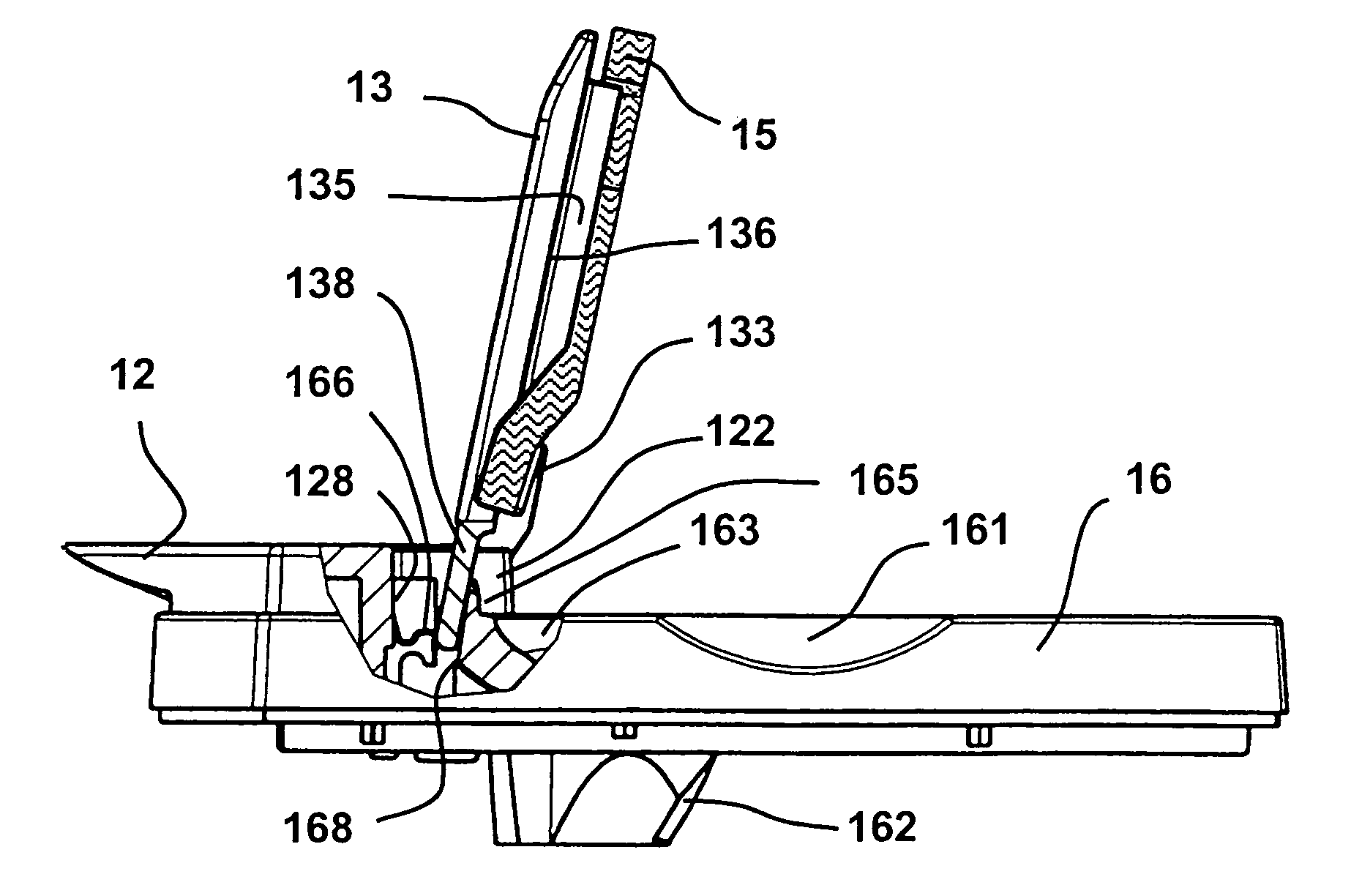
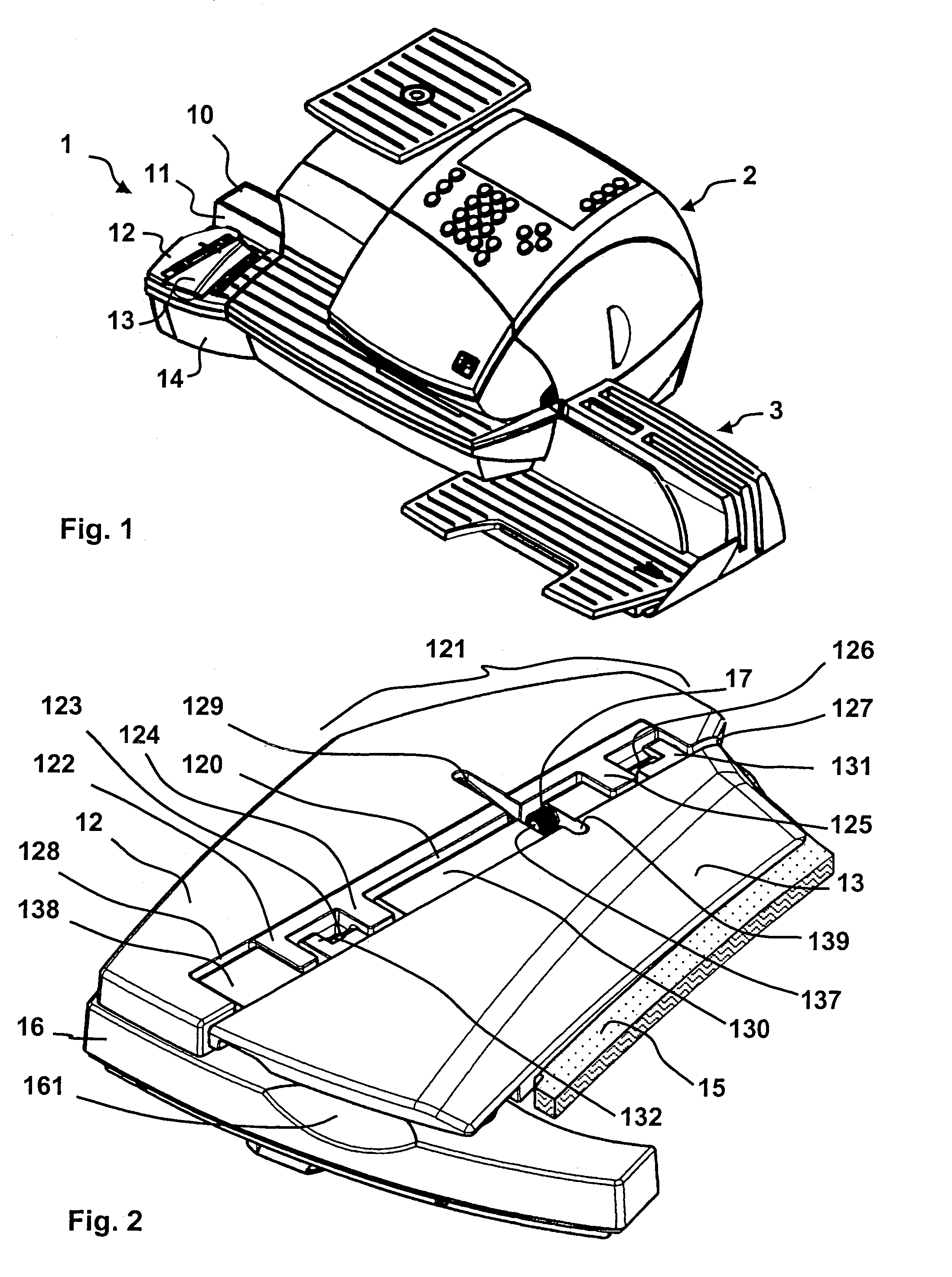
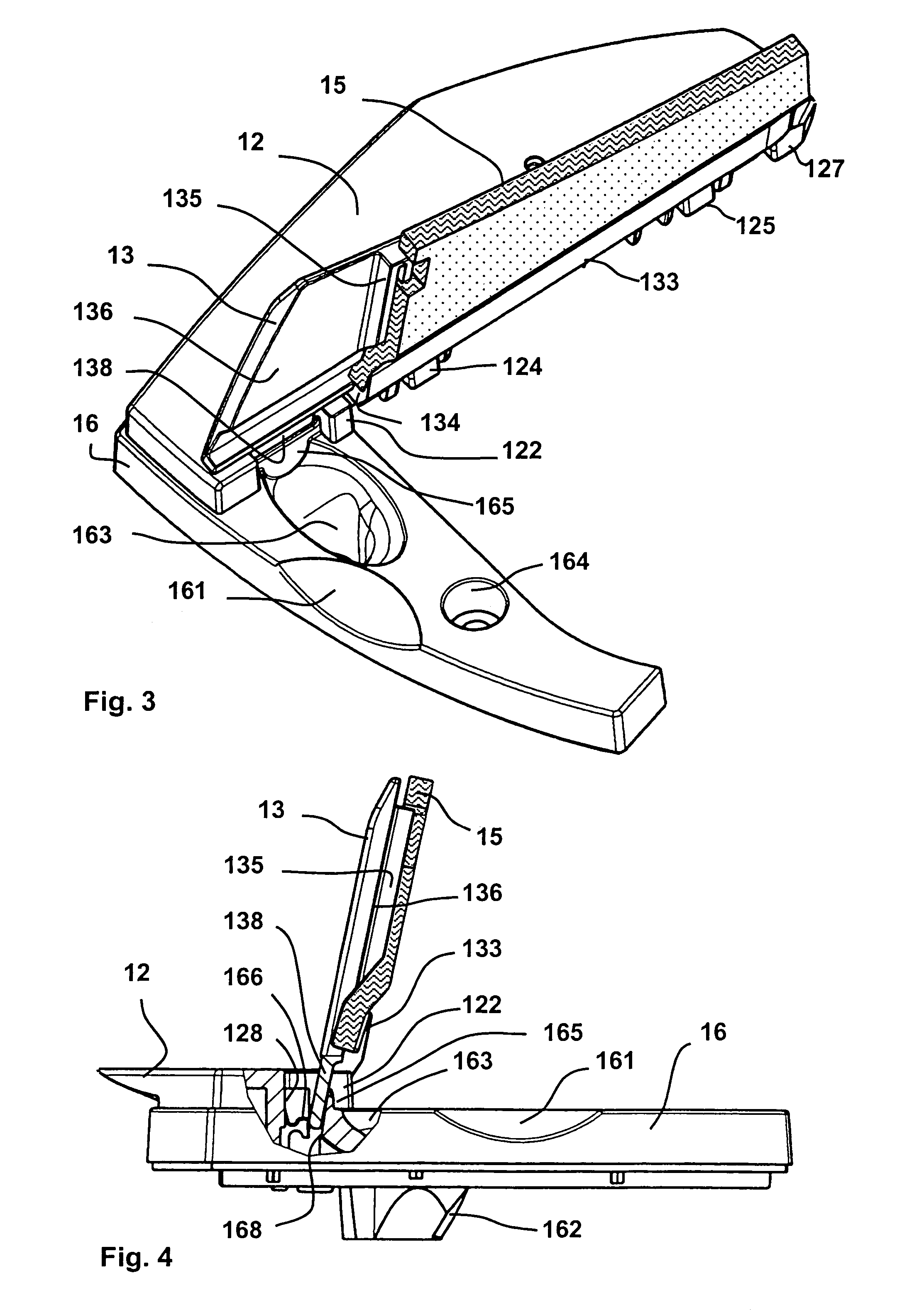
[0033]FIG. 1 is a perspective view of a system with a manual moistener 1, a franking machine 2 and a tray 3, the manually operated moistener 1 being upstream from the franking machine 2 in terms of the mail flow. The operation ensues with a slanted placement of a mail item on the manual moistener 1 with its flap away from the vertical letter placement wall 11. The front part of the flap, lying beneath the envelope body, is shifted against the sharp-edged, acute-angled front side of a blade 12. If the flap of the letter hooks on the blade 12, the operator notices a marked resistance, the flap is caught and, upon further shifting, the letter can be rotated into the blade 12 parallel to the vertical letter placement wall 11. The blade 12 does not extend upstream in terms of the mail flow over the region that is defined by the beginning of a surface of the upper part 10 and the vertical letter placement wall 11. A moistener rocker 13 disposed following the blade 12 wets the flap with mo...


PUM

PropertyMeasurementUnit
distanceaaaaaaaaaa
forceaaaaaaaaaa
widthaaaaaaaaaa

Abstract

A manually-operated moistener, to which a mail piece is supplied lying flat with a down-turned but not yet adhered flap on the underside of the envelope, has a blade in an upper part and a moistener rocker that can be opened upwardly and can be rotated with at least one locking contour on an associated hinge on the blade so as to be spring-supported as well as locked in a maintenance position. The upper part and a lower part of the moistener are connected by connection elements that can be detached only from above. An antibacterial upper moistening element is disposed in the upper part with a clamping region thereof in a clamping groove of the moistener rocker. A water transfer element protrudes into the lower part, which element is curved at its other, upper end. Both possess a shared contact surface for water transfer that is enlarged by the curvature.

Description

BACKGROUND OF THE INVENTION[0001]1. Field of the Invention[0002]The invention concerns a manually operated moistener of the type suitable for use with a mail processing machine as well as similar billing or mail processing apparatuses to which a postal item is manually supplied. Moisteners are used together with devices for sealing postal goods, in particular letter envelopes with a flap that has a water-activated adhesive edge.[0003]2. Description of the Prior Art[0004]A device for wetting and sealing the flap of a letter envelope supplied lying flat is a known from U.S. Pat. No. 799,304. The letter envelope has a flap on its upper side (in the device) and bears the receiver address on its underside.[0005]A wetting device for letter flaps in connection with franking machines is known from German 15 11 420. A letter envelope supplied flat has a turned-down but not yet adhered lap on its underside. The wetting device has a platform and a sword-shaped blade that can be rotated on a hi...

Claims


Application Information

Patent Timeline
Patent Type & Authority Patents(United States)
IPC IPC(8): B43M3/00B05C1/02B05C1/06B05C1/16B05C11/08B05C11/10B41L45/06B41L45/10B43M5/00B43M5/02B43M5/04B43M11/06
CPCB43M5/02B43M11/06
Inventor LUDTKE, DETLEF
Owner FRANCOTYP POSTALIA
Why Eureka
Try Eureka