Probe head for nuclear magnetic resonance measurements

a nuclear magnetic resonance and probe head technology, applied in the field of magnetic resonance, can solve the problems of deterioration of the quality factor of the resonance structure, hardly being tuned, and high dielectric losses, and achieve the effect of simple tuning

Active Publication Date: 2008-10-14
BRUKER BIOSPIN
View PDF19 Cites 14 Cited by
  • Summary
  • Abstract
  • Description
  • Claims
  • Application Information

AI Technical Summary

Benefits of technology

[0012]It is, therefore, an object underlying the invention to improve an MAS probe head of the type specified at the outset, such that the afore-mentioned disadvantages are avoided. In particular, the probe head shall be adapted to be operated at high frequencies of above 750 MHz, i.e. it shall have sufficient dimensions for receiving a sample, shall generate sufficiently strong high frequency magnetic field (B1), and shall be simple to tune. Moreover, the electrical field within the sample volume shall be as small as possible, such that the above-mentioned losses within the sample are likewise as small as possible.

Problems solved by technology

In this frequency range, solenoid coils are difficult to handle, because their dimensions become too small, so that no sufficient high frequency field strength (B1) may be generated, and, further, they may hardly be tuned.
This, in turn, results in high dielectric losses, not only for solid samples but in particular for liquid and for electrically conductive, for example salt-containing samples, all of which results in a deterioration of the quality factor of the resonance structure, which, in turn, worsens the measuring sensitivity.
In probe heads with MAS function, these circumstances present problems already in the frequency range above 750 MHz (17.6 T).

Method used


Image

  • Probe head for nuclear magnetic resonance measurements
  • Probe head for nuclear magnetic resonance measurements
  • Probe head for nuclear magnetic resonance measurements

Examples


Embodiment Construction

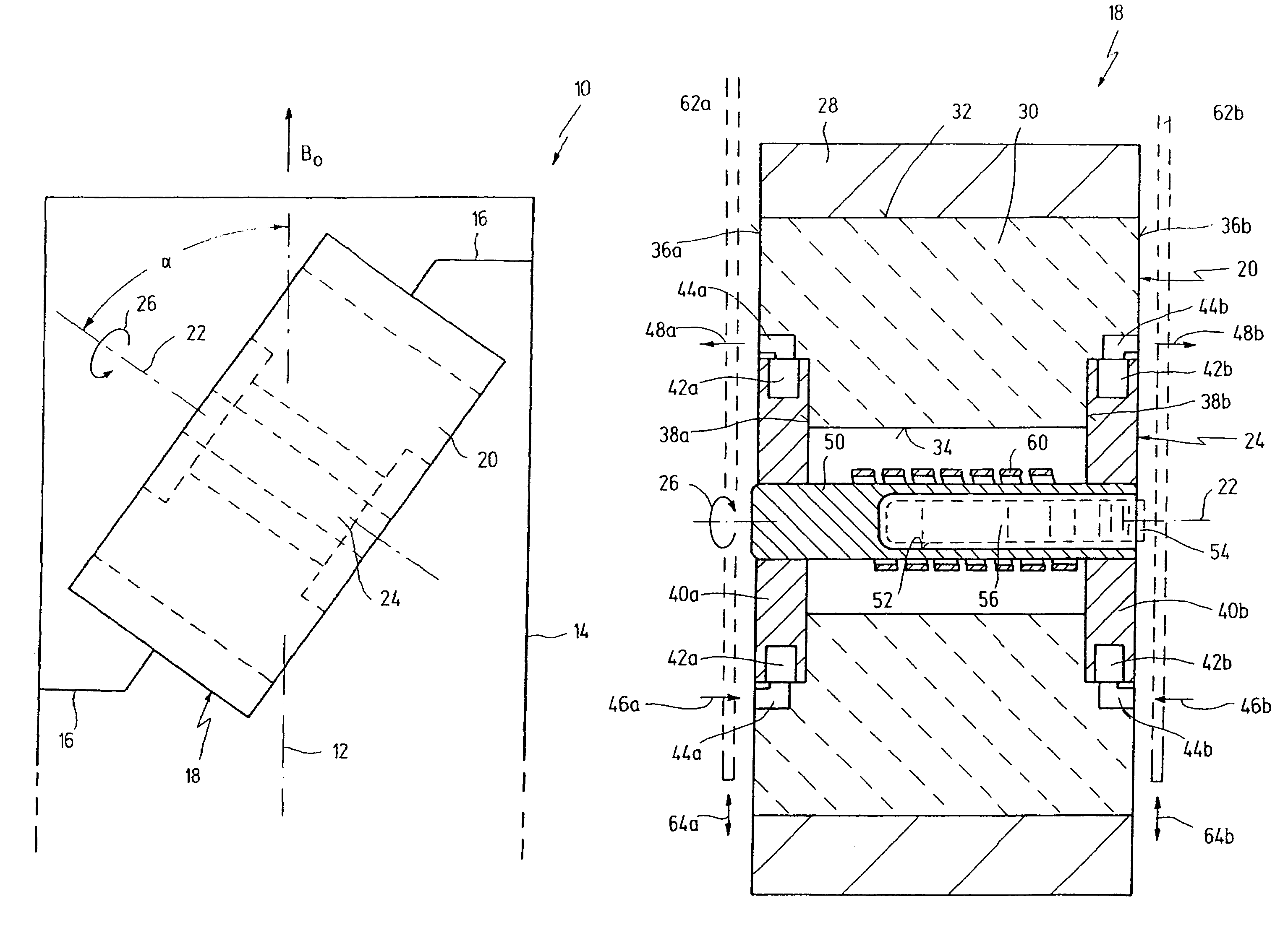
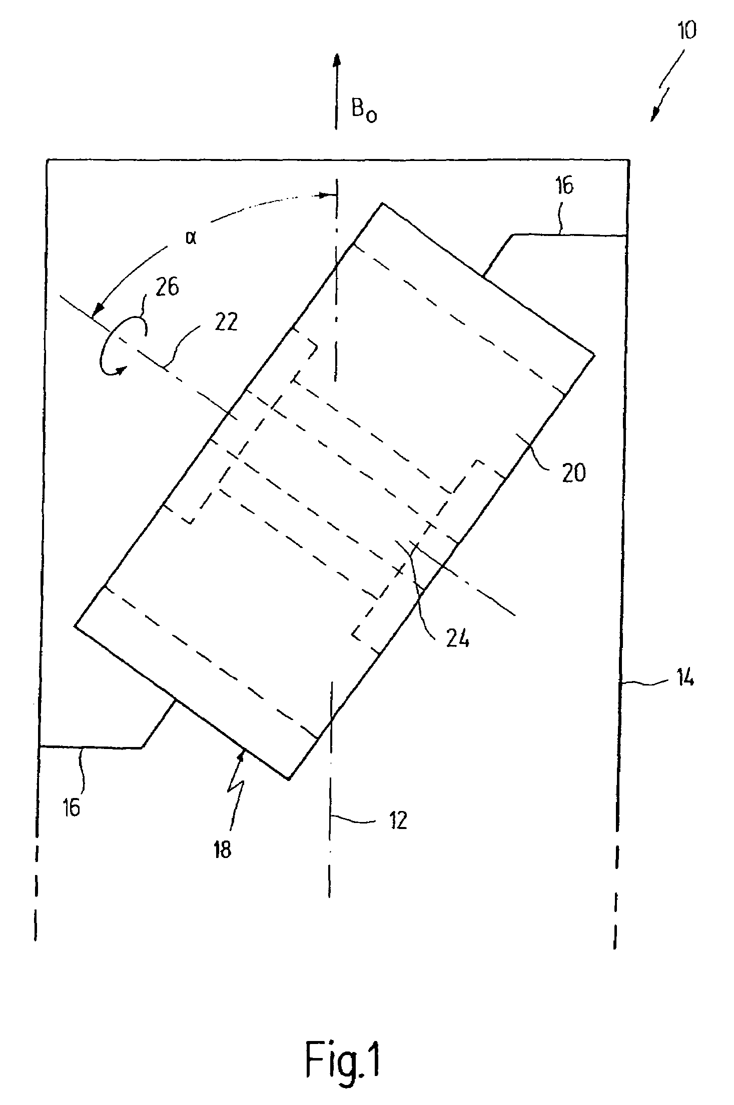
[0049]In FIG. 1, reference numeral 10 as a whole designates a probe head, as may be used for nuclear resonance measurements. Probe head 10 is of essentially cylindrical shape and has a longitudinal axis 12. Probe head 10 is surrounded by a housing 14 and may be inserted into a bore of a superconducting magnet. When doing so, longitudinal axis 12 coincides with the direction of constant magnetic field B0. By means of mounting elements 16, a sample holder 18 is attached to housing 14 or on a supporting structure of probe head 10. Sample holder 18 contains a stator 20 as well as a rotor 24 being journalled within stator 20 for rotation about an axis of rotation 22. The rotation of rotor 24 about axis of rotation 22 is indicated by an arrow 26.

[0050]Axis of rotation 22 is inclined relative to longitudinal axis 12, and, hence, also relative to the direction of constant magnetic field B0 by an angle α. Angle α is the so-called “magic angle” and amounts to 54.7°.

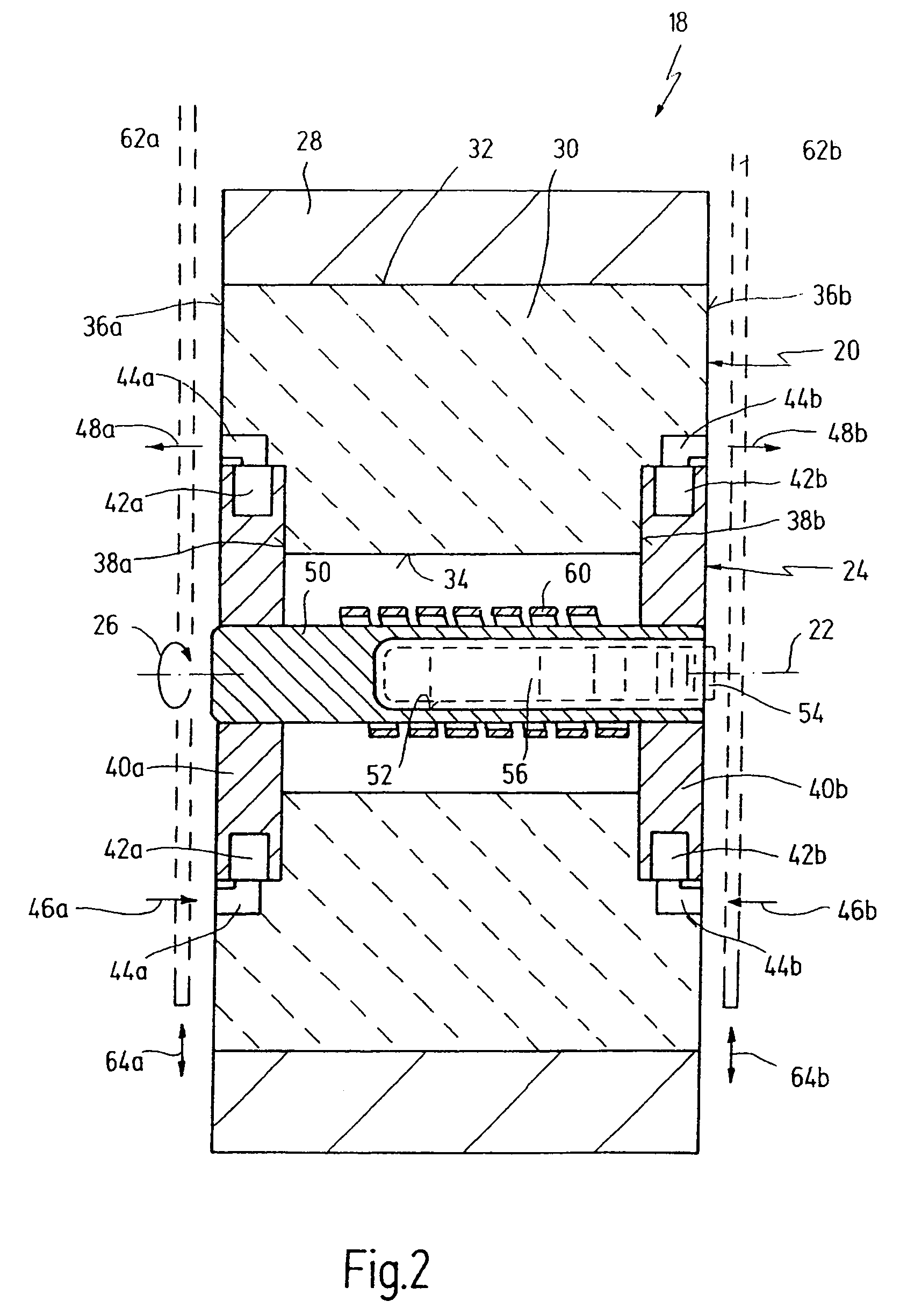
[0051]In FIGS. 2 and 3, fur...


PUM


Abstract

A probe head for nuclear magnetic resonance measurements comprises a sample holder having a stator and a rotor. The rotor is journalled for rotation about an axis of rotation within the stator. It is adapted for receiving a sample substance. The axis of rotation is inclined by an angle with respect to a longitudinal axis of the probe head. The stator is configured as a dielectric resonator.

Description

RELATED APPLICATIONS[0001]The present application claims priority of German patent application 10 2005 039 087.0 filed on Aug. 4, 2005.FIELD OF THE INVENTION[0002]The present invention is related to the field of magnetic resonance.[0003]More specifically, the invention is related to the field of nuclear magnetic resonance probe heads.[0004]Still more specifically, the invention is related to a probe head for nuclear magnetic resonance measurements, comprising a sample holder having a stator and a rotor, the rotor being journalled for rotation about an axis of rotation within the stator and being adapted for receiving a sample substance, the axis of rotation being inclined by an angle with respect to a longitudinal axis of the probe head.BACKGROUND OF THE INVENTION[0005]A probe head of the afore-mentioned kind is disclosed in EP 0 483 228 B1 (U.S. Pat. No. 5,298,864) and in DE 44 42 742 C1 (U.S. Pat. No. 5,760,586).[0006]In the field of nuclear magnetic resonance measurements (NMR) i...

Claims


Application Information

Patent Timeline
Patent Type & Authority Patents(United States)
IPC IPC(8): G01V3/00
CPCG01R33/307G01R33/34046G01R33/3453G01R33/30H01P7/10
Inventor KRAHN, ALEXANDERHOEFER, PETERENGELKE, FRANK
Owner BRUKER BIOSPIN
Why Eureka
Try Eureka