Ignition device
a technology of ignition plug and ignition plug, which is applied in the direction of electrical control, machines/engines, mechanical apparatus, etc., can solve the problems of increasing the number of control circuit components, increasing manufacturing costs, and increasing power consumption, so as to reduce the power supply power consumption in time of ignition plug discharge, suppress the deterioration of the ignition plug, and suppress the effect of power consumption
- Summary
- Abstract
- Description
- Claims
- Application Information
AI Technical Summary
Benefits of technology
Problems solved by technology
Method used
Image


Examples
first embodiment
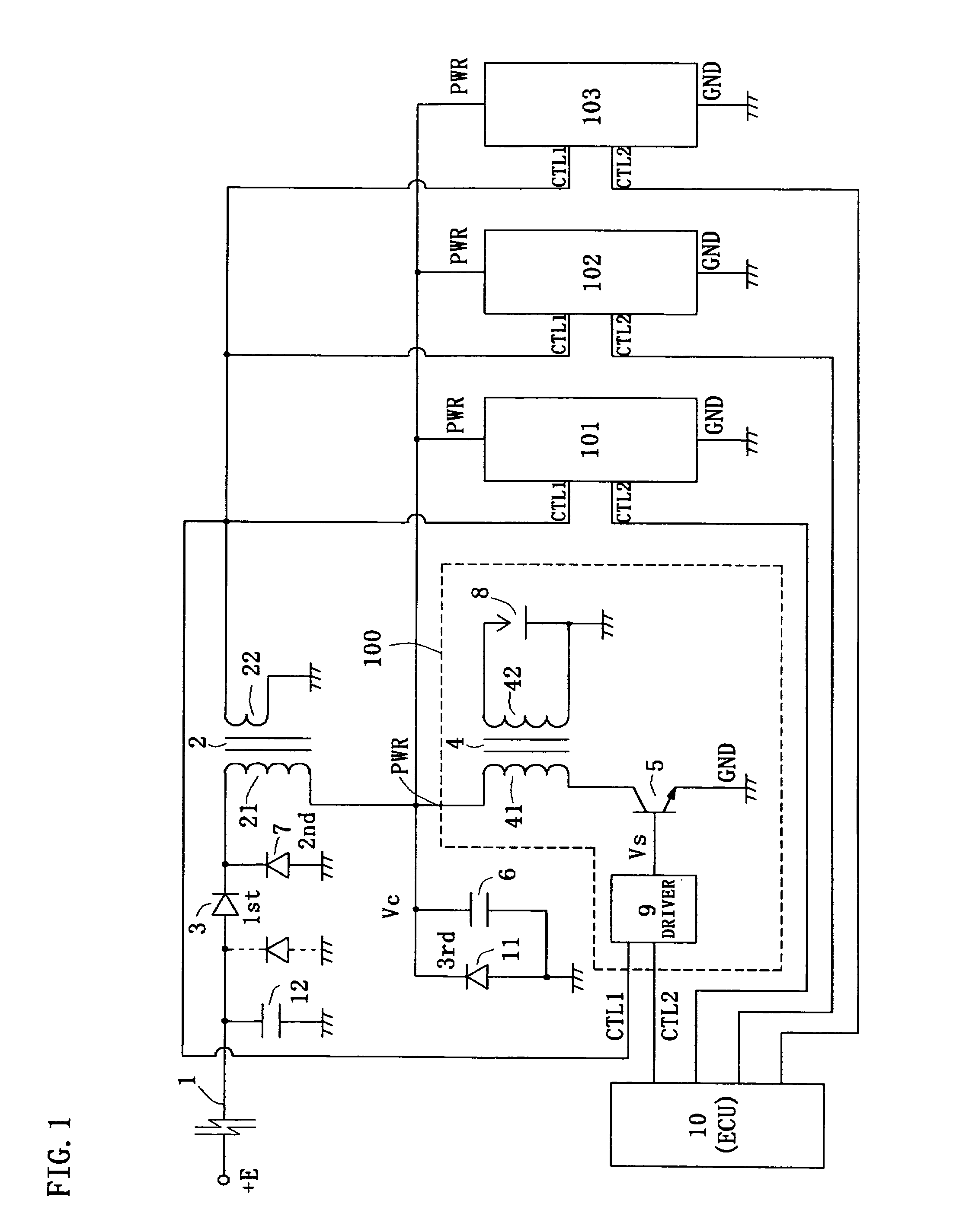
[0031]FIG. 1 is a circuit diagram showing an ignition device of a The ignition device shown corresponds to a four cylinder internal combustion (automobile engine herein) and the like, and four ignition units 100, 101, 102 and 103 having the same configuration operate by mainly being controlled by an electronic control unit (ECU) 10. The ignition units 100 to 103 produce high voltage at both ends of an ignition plug 8 by the ON / OFF operation of a switching element 5 and time sequentially discharges the ignition plug 8 of each ignition unit 100 to 103.
[0032]The ignition units 100 to 103 each includes a power supply terminal PWR, a first control terminal CTL1, a second control terminal CTL2, and a ground terminal GND. The detection output of the current detection coil 22 is provided to the first control terminal CTL1, and the control signal of different phase is provided from the ECU 10 to the second control terminal CTL2. The detection output of the current detection coil 22 is propo...
second embodiment
[0072]FIG. 7 is a circuit diagram showing an ignition device of a second embodiment, and the same reference characters are denoted for the same components as the ignition device of FIG. 1. The ignition device corresponds to the internal combustion of four cylinders and the like, and four ignition units 100, 101, 102 and 103 of the same configuration operate by mainly being controlled by the ECU 10. The detection output of the current detection coil 22 is provided to the first control terminal CTL1, and the control signal of different phase is provided from the ECU 10 to the second control terminal CTL2.
[0073]As shown in the figure, the direct current power supply E (42 V) is supplied by the battery through a series circuit consisting of the first diode 3 and the energy storage coil 21 to the power supply terminal PWR of the ignition units 100 to 103. The second diode 7 is connected so that the forward current flows from the ground terminal GND towards the energy storage coil 21, and...
PUM
 Abstract
Description
Claims
Application Information
 - R&D
- Intellectual Property
- Life Sciences
- Materials
- Tech Scout
- Unparalleled Data Quality
- Higher Quality Content
- 60% Fewer Hallucinations
Browse by: Latest US Patents, China's latest patents, Technical Efficacy Thesaurus, Application Domain, Technology Topic, Popular Technical Reports.
© 2025 PatSnap. All rights reserved.Legal|Privacy policy|Modern Slavery Act Transparency Statement|Sitemap|About US| Contact US: help@patsnap.com