Method and circuit for driving liquid crystal display and image display device

a liquid crystal display and image display technology, applied in the direction of electric digital data processing, instruments, computing, etc., can solve the problems of over-the-counter technology of the first conventional example, unbalance is produced between, flicker cannot be reduced, etc., to reduce flicker, reduce costs, and minimize flicker. effect of lin

Inactive Publication Date: 2009-04-14
VISTA PEAK VENTURES LLC
View PDF16 Cites 0 Cited by
  • Summary
  • Abstract
  • Description
  • Claims
  • Application Information

AI Technical Summary

Benefits of technology

[0015]In view of the above, it is an object of the present invention to provide a method for driving an LCD and its driving circuits capable of being constructed at low costs, of reducing a flicker that occurs when a monochromatic color is displayed or an image in colors other than a wh...

Problems solved by technology

However, the above technology of the first conventional example has a problem.
Generally, even when data signals being at a same potential but being different in polarity are fed to a signal electrode in order to drive a color LCD with alternating current, since, due to a characteristic of the TFT constructed of amorphous silicon, an on-current flowing when the data signal of negative polarity is applied is smaller than an on-current flowing when the data signal of positive polarity is allied, an unbalance is produced between when the data signal having a current of negative polarity flowing through a drain of the TFT is applied and when the data signal of positive polarity is applied.
As a result, there is a defect that the flicker cannot be reduced when an image in any monochromatic color is displayed or when an arbitrary image in colors other than the white color is displayed.
That is, when an adjuster, while visually identifying the line flicker that has already occurred, adjusts the common potential VCOM so that the line flicker can be minimized, it is possible to make the adjustment that can minimize the line flicker only in a local region of the entire display screen, however, it...

Method used


Image

  • Method and circuit for driving liquid crystal display and image display device
  • Method and circuit for driving liquid crystal display and image display device
  • Method and circuit for driving liquid crystal display and image display device

Examples


embodiment

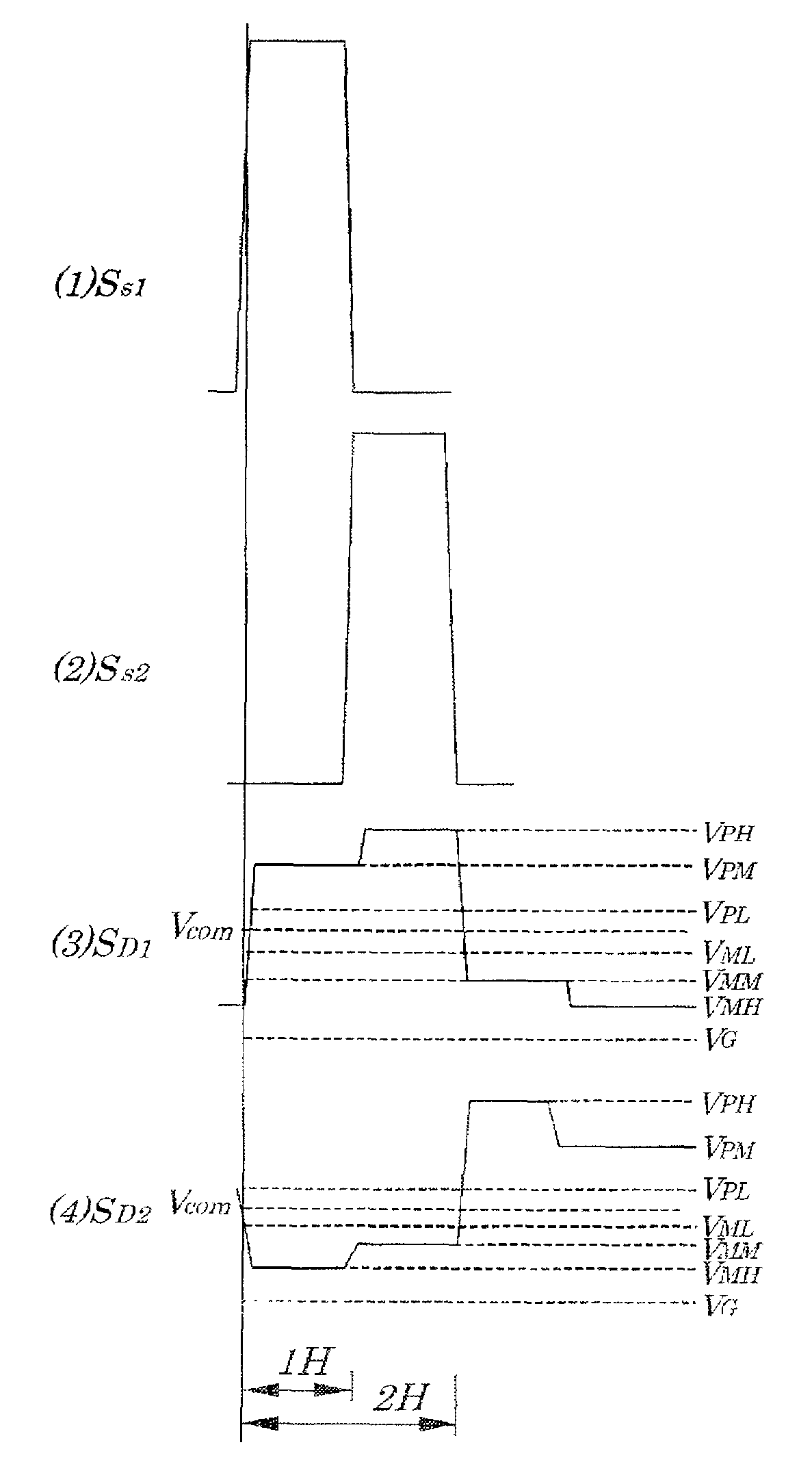
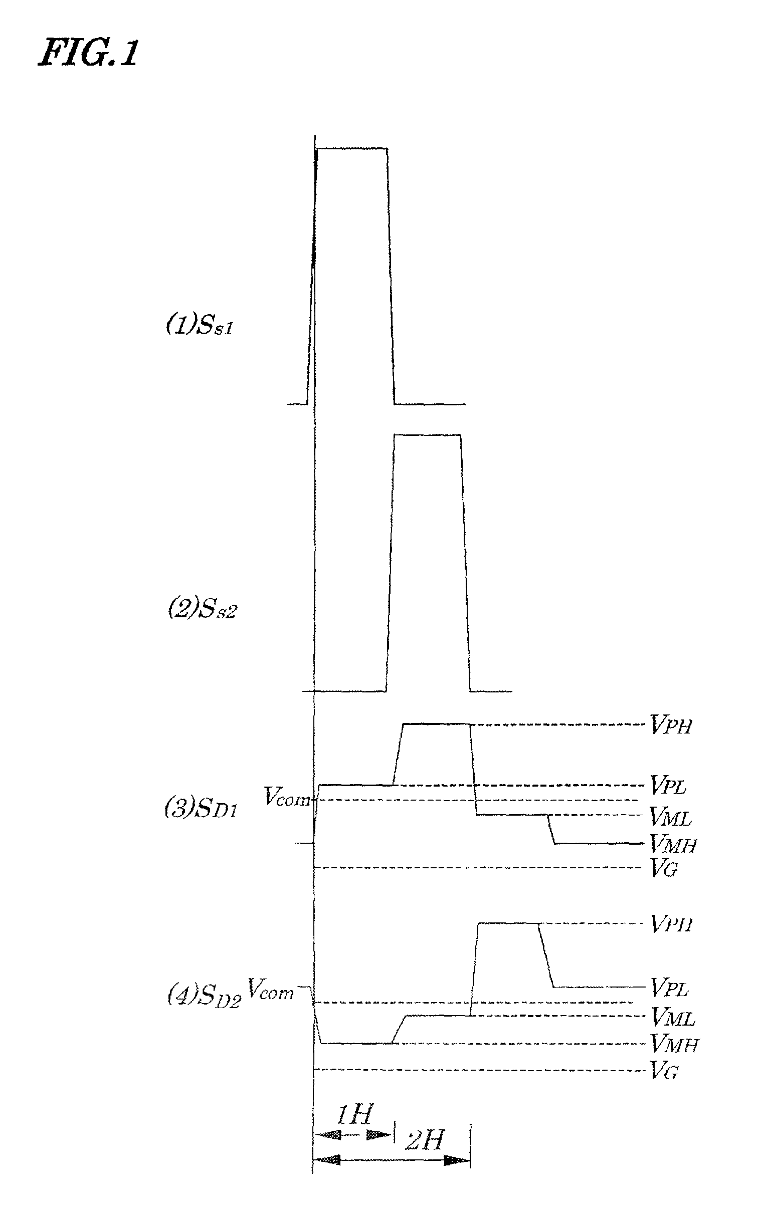
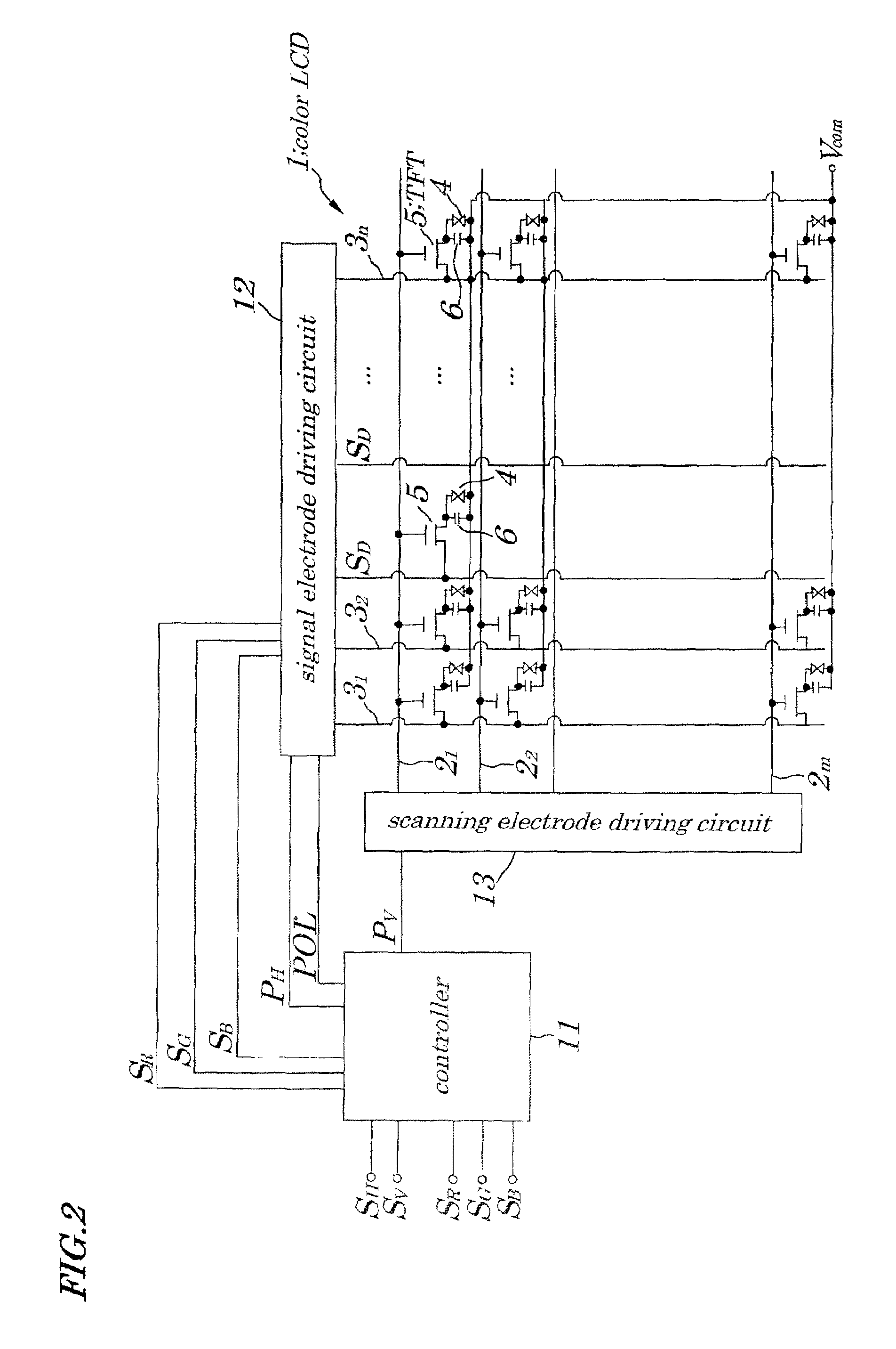
[0063]FIG. 1 is a timing chart explaining a method for driving a color LCD 1 according to an embodiment of the present invention. FIG. 2 is a schematic block diagram showing configurations of a driving circuit for the color LCD 1 according to the embodiment of the present invention. The color LCD 1 shown in FIG. 2 is an active-matrix color LCD using, for example, a TFT (Thin Film Transistor) constructed of amorphous silicon as a switching element. In the above color LCD 1, each of pixel portions is mounted at an intersection of each of “m” (m is a natural number) pieces of scanning electrodes (gate lines) 21 to 2m placed at specified intervals in a row direction and each of “n” (n is a natural number) pieces of signal electrodes (source lines) 31 to 3n placed at specified intervals in a column direction. Moreover, in each pixel portion, a liquid crystal cell 4 being equivalently a capacitive load, a TFT 5 whose drain is connected to one terminal of a corresponding liquid crystal cel...


PUM


Abstract

A method for driving an LCD and its driving circuits are provided which are capable of being constructed at low costs, of reducing a flicker that occurs when a monochromatic color is displayed or an arbitrary image is displayed and of simultaneously making an adjustment for minimizing a line flicker and flicker occurring on an entire screen and of being applied to application areas in which a display is made more high-definition and a screen is made larger.
The LCD is driven in a manner that a polarity of a data signal is reversed for every two scanning electrodes and for every signal electrode and the data signal having the reversed polarity is sequentially fed to each of signal electrodes.

Description

BACKGROUND OF THE INVENTION[0001]1. Field of the Invention[0002]The present invention relates to a method for driving a liquid crystal display (hereinafter referred simply to as an LCD), its driving circuits and an image display device and more particularly to the method for driving the LCD which is used as a display device for a personal computer or a like and in which liquid crystal cells are arranged in a matrix form, to its driving circuits and the image display device equipped with such the driving circuits for the LCD.[0003]The present application claims priority of Japanese Patent Application No. 2000-244963 filed on Aug. 11, 2000, which is hereby incorporated by reference.[0004]2. Description of the Related Art[0005]FIG. 12 is a schematic block diagram showing an example of configurations of a driving circuit of a conventional color LCD 41 disclosed in Japanese Laid-open Patent Application No. Hei 03-083014. Hereinafter, the disclosed technology is called a first conventiona...

Claims


Application Information

Patent Timeline
IPC IPC(8): G09G3/36G02F1/133G09G3/20
CPCG09G3/3607G09G3/3614G09G3/3648G09G2320/0247G02F1/133
Inventor HOSOYAMADA, SHUNICHI
Owner VISTA PEAK VENTURES LLC
Why Eureka
Try Eureka