Turbine airfoil cooling system with near wall vortex cooling chambers

a cooling system and turbine airfoil technology, which is applied in the direction of blade accessories, engine fuctions, machines/engines, etc., can solve the problems of reducing the useful life of the turbine blade, the possibility of failure, and localized hot spots, so as to maximize the potential of using the total available cooling fluid pressure

Inactive Publication Date: 2009-04-21
SIEMENS ENERGY INC
View PDF18 Cites 19 Cited by
  • Summary
  • Abstract
  • Description
  • Claims
  • Application Information

AI Technical Summary

Benefits of technology

[0011]Another advantage of this invention is that each individual vortex cooling chamber may be designed based on the airfoil local external heat load to achieve a desired local metal temperature level by varying the tangential velocities and pressure levels within each vortex cooling chamber.
[0012]Yet another advantage of this invention is that the flow of cooling fluids through the central cooling fluid chambers, through the leading edge cooling channel, through the vortex cooling chambers, and through the trailing edge bleed slots maximize the potential of using total available cooling fluid pressure.

Problems solved by technology

In addition, turbine blades often contain cooling systems for prolonging the life of the blades and reducing the likelihood of failure as a result of excessive temperatures.
However, centrifugal forces and air flow at boundary layers often prevent some areas of the turbine blade from being adequately cooled, which results in the formation of localized hot spots.
Localized hot spots, depending on their location, can reduce the useful life of a turbine blade and can damage a turbine blade to an extent necessitating replacement of the blade.

Method used


Image

  • Turbine airfoil cooling system with near wall vortex cooling chambers
  • Turbine airfoil cooling system with near wall vortex cooling chambers
  • Turbine airfoil cooling system with near wall vortex cooling chambers

Examples


Embodiment Construction

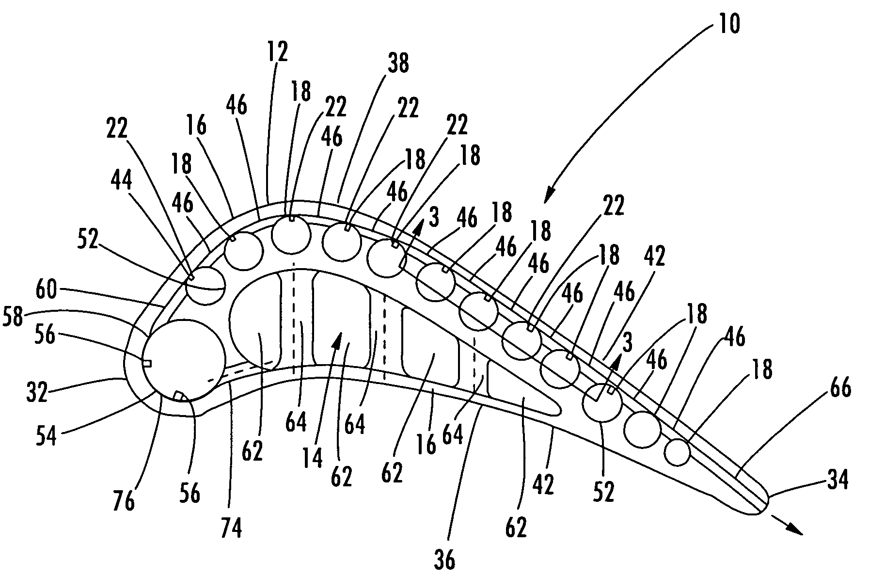
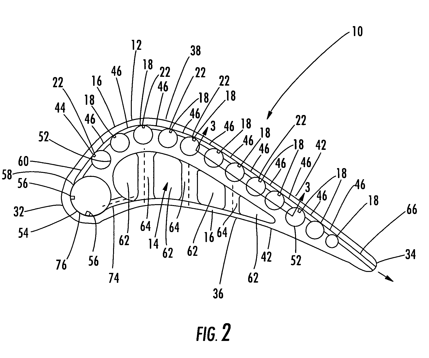
[0019]As shown in FIGS. 1-4, this invention is directed to a turbine airfoil cooling system 10 for a turbine airfoil 12 used in turbine engines. In particular, the turbine airfoil cooling system 10 includes a plurality of internal cavities 14, as shown in FIG. 2, positioned between outer walls 16 of the turbine airfoil 12. The cooling system 10 may include a plurality of vortex cooling chambers 18 in the outer wall 16 that may be adapted to receive cooling fluids from the internal cavity 14, meter the flow of cooling fluids through the outer wall 16, and release the cooling fluids from the airfoil 12 through one or more trailing edge bleed slots 20.

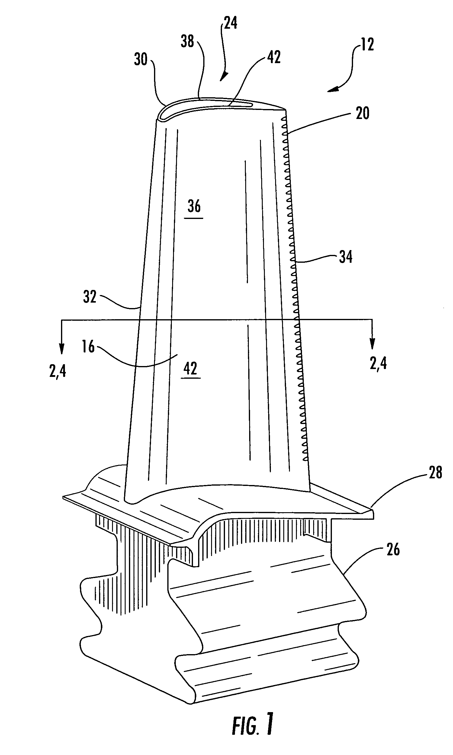
[0020]The turbine airfoil 12 may be formed from a generally elongated, hollow airfoil 24 coupled to a root 26 at a platform 28. The turbine airfoil 12 may be formed from conventional metals or other acceptable materials. The generally elongated airfoil 24 may extend from the root 26 to a tip section 30 and include a leading edge 32 and tr...


PUM


Abstract

A cooling system for a turbine airfoil of a turbine engine having a plurality of vortex cooling chambers positioned in an outer wall defining a suction side of the turbine airfoil. The vortex cooling chambers may extend generally spanwise and be positioned in the outer wall from a position in close proximity to the leading edge to the trailing edge. The vortex cooling chambers may form a continuous cooling fluid flow path from the leading edge to the trailing edge in the outer wall forming the suction side of the turbine airfoil. The vortex cooling chambers may be fed with cooling air from a central cooling fluid chamber through a leading edge cooling chamber.

Description

FIELD OF THE INVENTION[0001]This invention is directed generally to turbine airfoils, and more particularly to cooling systems in hollow turbine airfoils.BACKGROUND[0002]Typically, gas turbine engines include a compressor for compressing air, a combustor for mixing the compressed air with fuel and igniting the mixture, and a turbine blade assembly for producing power. Combustors often operate at high temperatures that may exceed 2,500 degrees Fahrenheit. Typical turbine combustor configurations expose turbine blade assemblies to these high temperatures. As a result, turbine blades must be made of materials capable of withstanding such high temperatures. In addition, turbine blades often contain cooling systems for prolonging the life of the blades and reducing the likelihood of failure as a result of excessive temperatures.[0003]Typically, turbine blades are formed from a root portion having a platform at one end and an elongated portion forming a blade that extends outwardly from t...

Claims


Application Information

Patent Timeline
Patent Type & Authority Patents(United States)
IPC IPC(8): F01D5/18
CPCF01D5/187F05D2260/2212F05D2240/127
Inventor LIANG, GEORGE
Owner SIEMENS ENERGY INC
Why Eureka
Try Eureka