Pile driver for use in a confined space with limited head room

a module and driver technology, applied in the direction of piles/piles, protective foundations, constructions, etc., can solve the problems of inability to move to work in confined spaces, many small pile lengths, and disadvantageous machines, etc., and achieve the effect of maximising potential

Inactive Publication Date: 2013-10-15
ONG CHIN CHAI
View PDF18 Cites 0 Cited by
  • Summary
  • Abstract
  • Description
  • Claims
  • Application Information

AI Technical Summary

Benefits of technology

[0015]The pile driver has no obstructing horizontal members thus allowing the pile to be displaced horizontally and vertically aligned into the clamping block which is moved to the ground level or even below the foundation sub-structure.
[0024]It should be appreciated that to maximise the potential of the present invention, the modular pile driver can be inter-connected into an assembly surrounding the foundation in order to use the push and pull method to utilize the adjacent frictional resistances of the driven piles as reactions to drive the pile with greater force than the building weight.

Problems solved by technology

This kind of machines is disadvantageous and clearly cannot be moved to work in confined spaces like in a basement of a building.
Using this method is obviously disadvantageous because the pile length will be limited to the clear distance taken from the tip of the hydraulic ram to the top of the existing driven pile in the ground, and moreover only short pile can be driven to avoid buckling.
In U.S. Pat. No. 5,433,556 and U.S. Pat. No. 2,204,283, a simply pressing down on the pile's top surface requires that the foundation has to be excavated and jacked against the base of the foundation to the top of the pile that is being driven; clearly this is cumbersome, difficult and can only drive many small pile lengths.
U.S. Pat. No. 5,722,798 and U.S. Pat. No. 4,925,345 has disadvantages in the loading method even though using a side gripping mechanism as it requires that the pile be slotted vertically from the top into an opening of a fixed horizontal thrust member which is located some height above the ground, therefore reducing the maximum possible pile length to be driven.
In another case, U.S. Pat. No. 5,135,335 and U.S. Pat. No. 4,411,408 employ slots in the pile to be used as gripping mechanism, but these slots will be difficult to fabricate in full section such as concrete square pile as it may initiate crack formations.
EP1806455A1 uses top hydraulic clamps in the pull and push method as commonly used in driving sheet piles in a row, however since these pile gripping mechanism is applied from the top of the piles it is therefore unable to drive maximum pile length.
The pile drivers mentioned in the above prior arts have drawbacks such as having either tall frame, heavy and bulky structure or inconvenient top loading of pile which is difficult to mobilise into a small confined space with limited head room and drive the pile at or below the foundation sub-structure.

Method used


Image

  • Pile driver for use in a confined space with limited head room
  • Pile driver for use in a confined space with limited head room
  • Pile driver for use in a confined space with limited head room

Examples


Embodiment Construction

[0034]Referring to the drawings, like numerals indicate like components to facilitate explanation. In order to differentiate two separate entities belonging to like components, a suffix “a” or “b” is used to denote the first and second entity.

[0035]Components of the Pile Driver

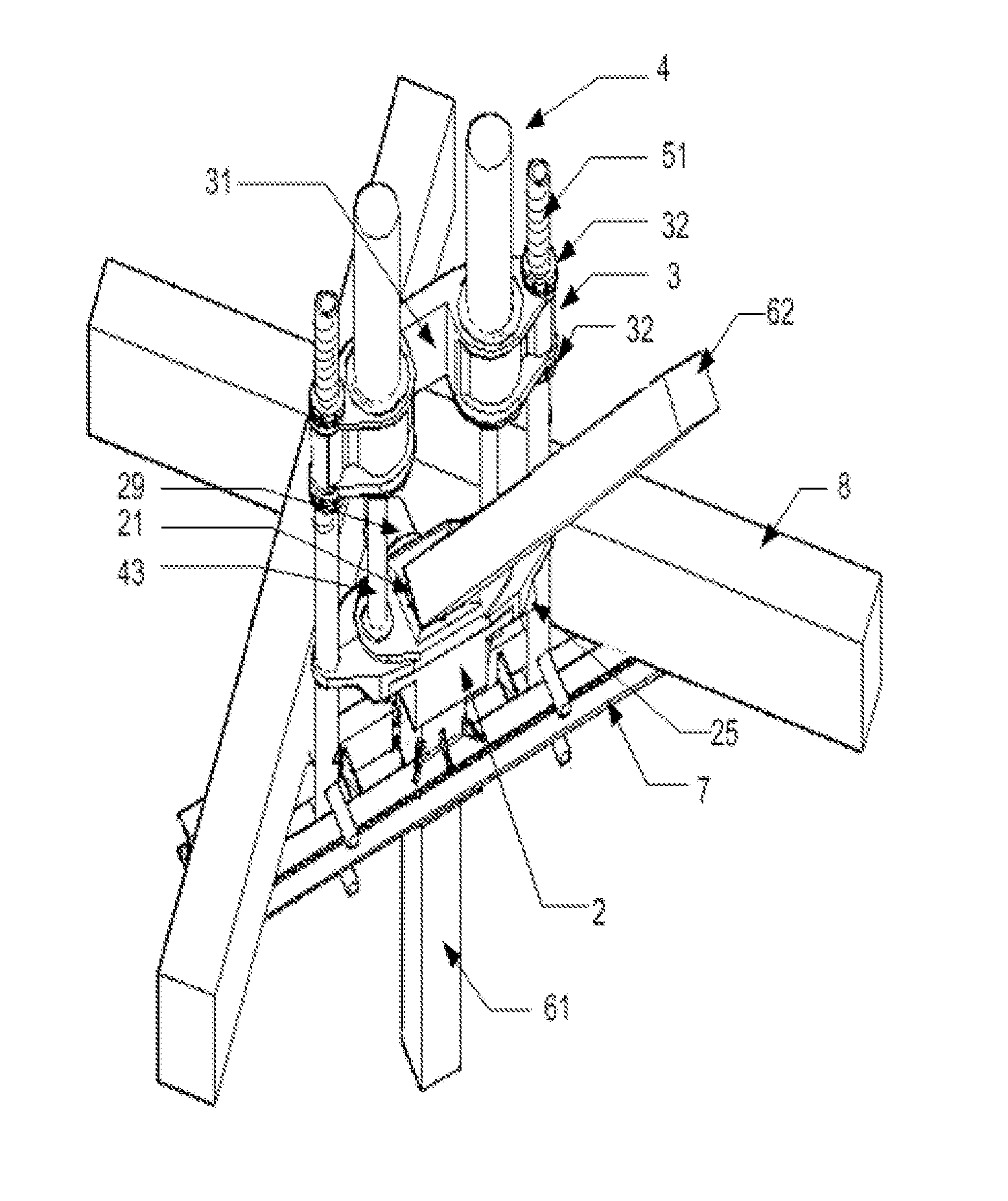
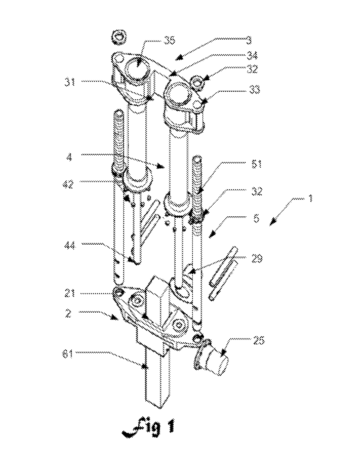
[0036]FIG. 1 shows the components of the pile driver (1) according to one embodiment of the present invention. In the broadest aspect of the present invention, the pile driver (1) comprises of an underpinning pile (61), a clamping block (2), a thrust block frame structure (3) and a pair of vertical hydraulic jacks (4).

[0037]The underpinning pile (61) can be a tabular and made of any kind of material such as steel, timber or concrete. The thrust block frame structure (3) consists of a C-shaped horizontal beam (34) with a side opening (31) made of steel that is heavily designed to resists twisting and accommodates a pair of vertical hydraulic jacks (4) and two vertical holding frame members (5).

[0038]The thrust ...


PUM


Abstract

A piling driver (1) to drive a high capacity and maximum continuous length of underpinning pile (61, 62) of at least equal to the clear floor height of a building. The modular piling driver (1) can be assembled on site to drive a pile into the ground within a small confined space under a limited head room comprising of; an underpinning pile (61, 62), a clamping block (2) with horizontal hydraulic clamps (25, 29), a thrust block frame structure (3) with a C-shaped horizontal beam (34) supporting a pair of vertical hydraulic jacks' (4) with corresponding rams (43) that drives the clamping block (2) along the two vertical holding frame members (5) which is supported by a pair of upper and lower locking pins (54) on to the parallel beams (7) that will bear against the soffit of the foundations (8). A method of push pull piling characterized in that apart from only using the counterweight is to utilize the pull resisting force of the adjacent underpinning piles (61a, 61b, 61c) through a system of inter-connecting at least two units of the piling driver (1) into an assembly (9).

Description

CROSS-REFERENCE TO RELATED APPLICATION[0001]The instant application claims priority to PCT International Application No. PCT / MY2009 / 000163, filed on Oct. 1, 2009, pending, and Malaysian Patent Application No. PI 20084705, filed Nov. 21, 2008, pending, the entire specifications of both of which are expressly incorporated herein by reference.1. TECHNICAL FIELD OF THE INVENTION[0002]The present invention relates to a modular piling driver to drive a high capacity and maximum continuous length of underpinning pile (62) pile of at least equal to the clear floor height of a building. Further, the pile driver can also insert the pile at or below the foundation sub-structure in confined spaces to save material without having to cut-off extra length. In addition to this advantage, a series of light weight modular basic unit of the present invention can be manually connected together to form an assembly within the excavated foundation to drive piles.[0003]However, it is also noted that the pr...

Claims


Application Information

Patent Timeline
Patent Type & Authority Patents(United States)
IPC IPC(8): E02D7/00
CPCE02D7/14E02D7/20E02D11/00E02D35/00
Inventor ONG, CHIN CHAI
Owner ONG CHIN CHAI
Why Eureka
Try Eureka