Displacement control mechanism for variable displacement compressor

a variable-discharge compressor and displacement control technology, which is applied in the direction of positive-discharge liquid engines, machines/engines, lighting and heating apparatus, etc., can solve the problems of increasing reducing the displacement, and reducing the pressure in the crank chamber, so as to reduce the opening degree and the compressor speed is high.

Inactive Publication Date: 2009-04-28
TOYOTA IND CORP
View PDF26 Cites 8 Cited by
  • Summary
  • Abstract
  • Description
  • Claims
  • Application Information

AI Technical Summary

Benefits of technology

[0007]Accordingly, it is an objective of the present invention to prevent a variable displacement compressor from operating with a large displacement when there is insufficient amount of refrigerant or when the speed of the compressor is high.
[0008]To achieve the foregoing objectives, the present invention provides a displacement control mechanism for a variable displacement compressor that compresses refrigerant in a suction pressure zone and delivers the compressed refrigerant to a discharge pressure zone. The compressor includes a control pressure chamber, a supply passage that connects the discharge pressure zone to the control pressure chamber, and a delivery passage that connects the suction pressure zone to the control pressure chamber. The displacement control mechanism permits refrigerant in the discharge pressure zone to be supplied to the control pressure chamber through the supply passage and permits refrigerant in the control pressure chamber to be delivered to the suction pressure zone through the delivery passage, thereby adjusting the pressure in the control pressure chamber to control the displacement of the compressor. The displacement control mechanism includes a valve hole forming a part of the supply passage or the delivery passage, and a valve body for opening and closing the valve hole. A pressure sensing device urges the valve body with a force that corresponds to a pressure difference between a first position and a second position, which are located in the discharge pressure zone. When the pressure in the suction pressure zone falls below a predetermined reference pressure, a displacing device produces a driving force for displacing the valve body. When the valve hole forms a part of the supply passage, the displacing device displaces the valve body in a direction increasing the opening degree of the valve hole with the driving force. When the valve hole forms a part of the delivery passage, the displacing device displaces the valve body in a direction reducing the opening degree of the valve hole with the driving force.

Problems solved by technology

This increases the pressure in the crank chamber, and thus reduces the displacement.
This decreases the pressure in the crank chamber, and thus increases the displacement.
Such high speed and large displacement operation applies a great load on the compressor, particularly on the swash plate, and is therefore unfavorable in terms of the reliability.
Also, due to the shortage of the refrigerant gas, the discharge pressure cannot be increased.
Therefore, high speed and large displacement operation with an insufficient amount of refrigerant gas causes the following disadvantages, for example, to a compressor having a hinge mechanism disclosed in Japanese Laid-Open Patent Publication No. 2004-108245.
In the case of a compressor equipped with such a hinge mechanism, high speed and large displacement operation may cause inertial force of pistons to surpass the compression reaction force.
Also, even if there is a sufficient amount of refrigerant gas, high speed and large displacement operation of a variable displacement compressor is not favorable in terms of the reliability.
Further, even if there is a sufficient amount of refrigerant gas, a great inertial force of the pistons can cause the inclination angle of the swash plate to surpass the predetermined maximum inclination angle in the case of the hinge mechanism disclosed in Japanese Laid-Open Patent Publication No. 2004-108245.

Method used


Image

  • Displacement control mechanism for variable displacement compressor
  • Displacement control mechanism for variable displacement compressor
  • Displacement control mechanism for variable displacement compressor

Examples


first embodiment

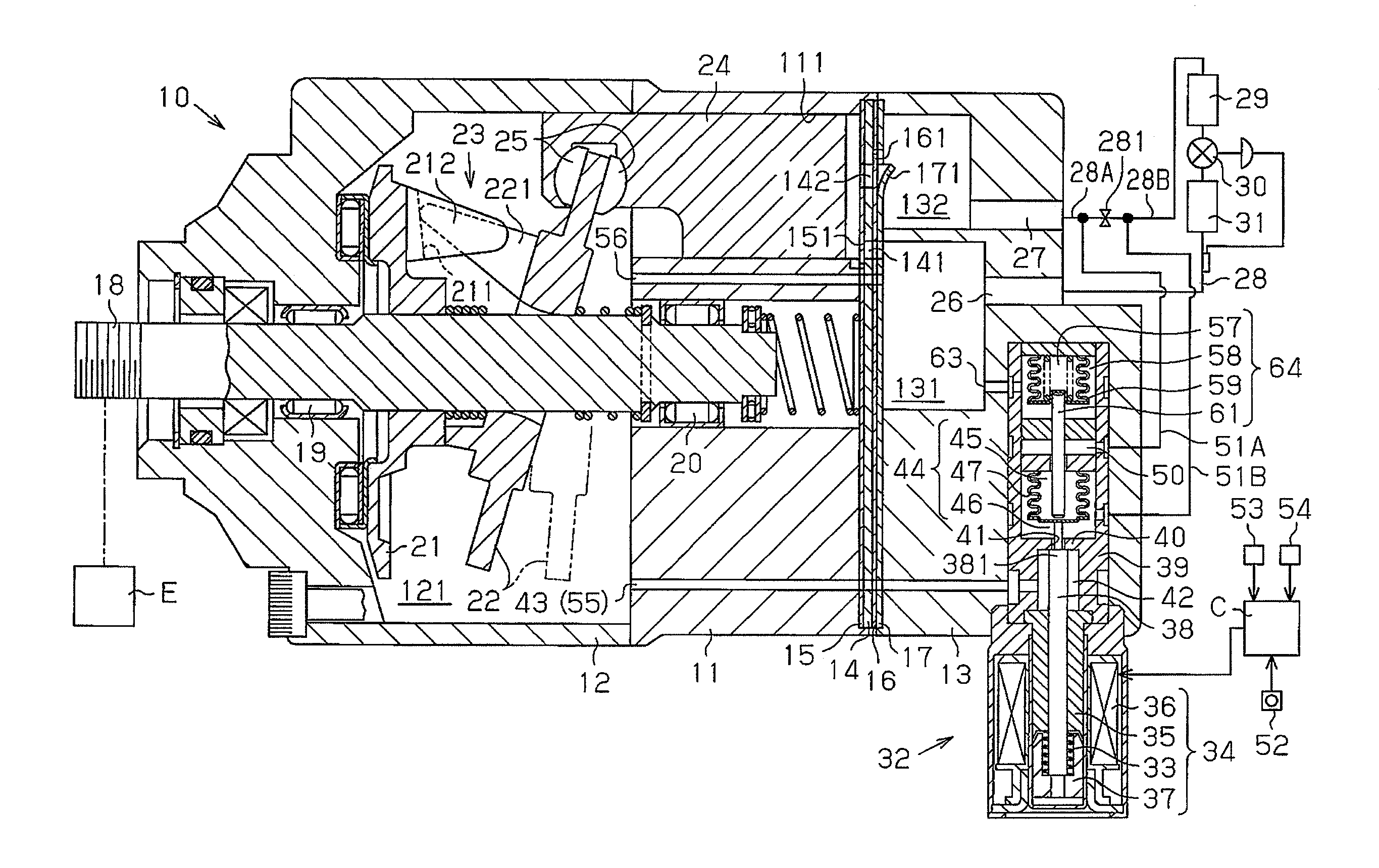
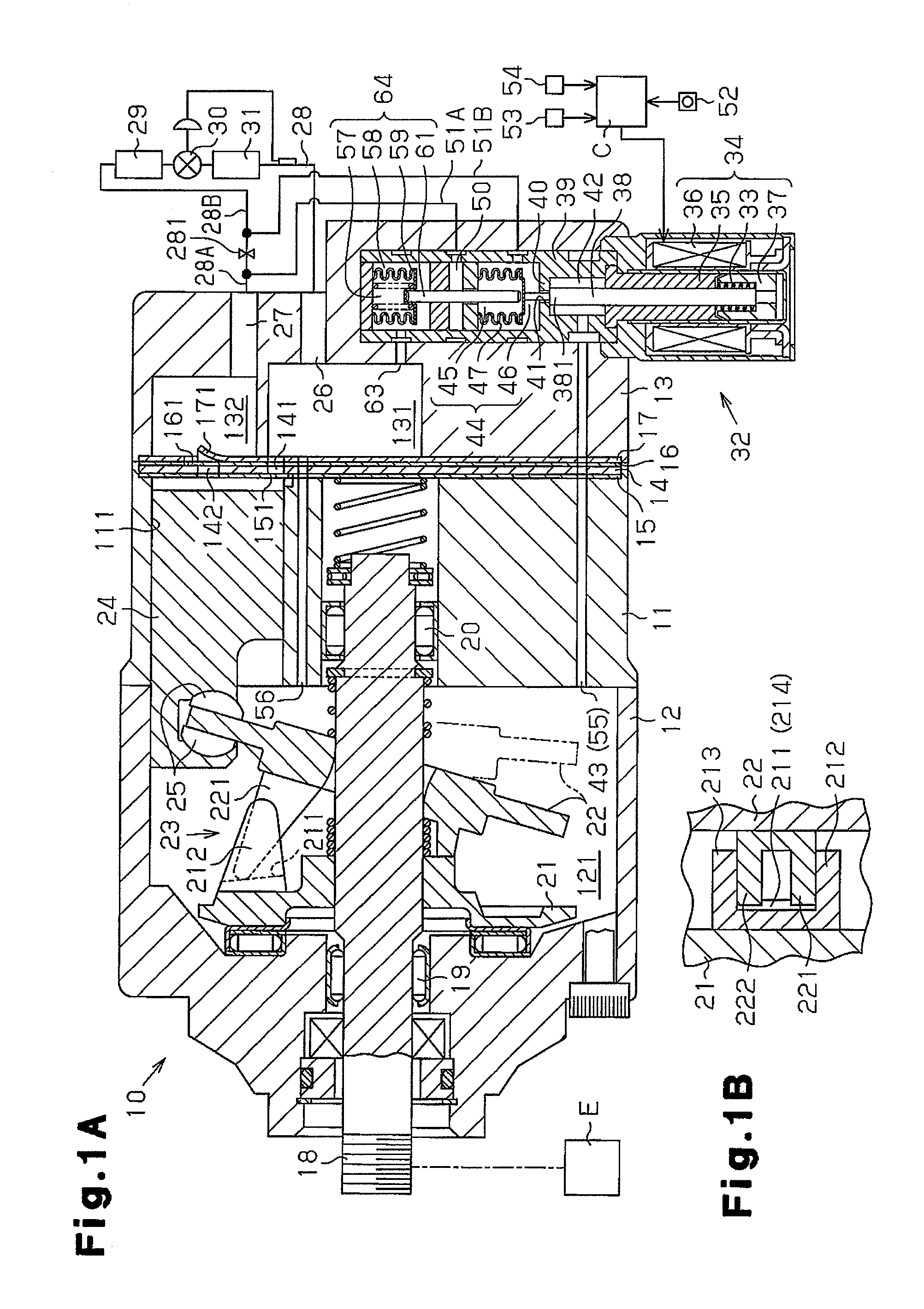
[0019]the present invention will now be described with reference to FIGS. 1A to 2B.

[0020]As shown in FIG. 1A, a front housing member 12 is secured to the front end of a cylinder block 11. A rear housing member 13 is secured to the rear end of the cylinder block 11 with a valve plate 14, valve flap plates 15, 16, and a retainer plate 17 arranged in between. The cylinder block 11, the front housing member 12, and the rear housing member 13 form a housing of a compressor 10.

[0021]The front housing member 12 and the cylinder block 11 define a control pressure chamber 121. The front housing member 12 and the cylinder block 11 rotatably support a rotary shaft 18 with radial bearings 19, 20. The rotary shaft 18 projects from the control pressure chamber 121 to the outside, and receives power from a vehicle engine E, which is an external power source, through an electromagnetic clutch (not shown).

[0022]A rotary support 21 is fixed to the rotary shaft 18, and a swash plate 22 is supported on...
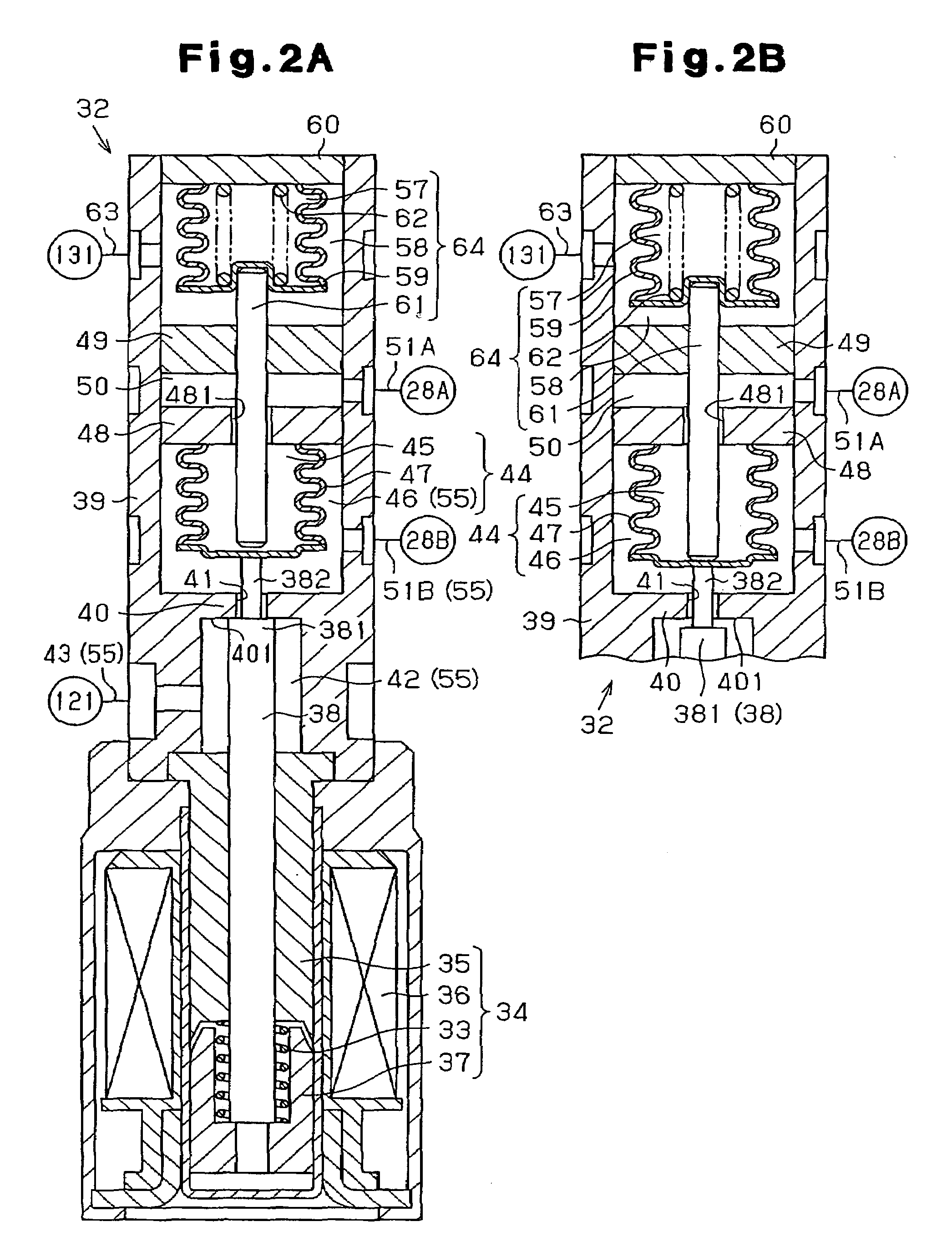
second embodiment

[0053]A second embodiment according to the present invention will now be described with reference to FIGS. 3A and 3B. Same reference numerals are used for those components which are the same as the corresponding components of the first embodiment. The support 48A supporting the first bellows 47 is slidably inserted into the housing 39. A through hole 482 is formed in the support 48A. The first pressure sensing chamber 45 communicates with the refrigerant introduction chamber 50 through the through hole 482. A transmission rod 61A serving as a displacement transmitter extends through the partition 49 and can contact the support 48A. The first pressure chamber 57, the second pressure chamber 58, the second bellows 59, the transmission rod 61A, and the urging spring 62 form a displacing device 64A, which is installed in a displacement control valve 32A.

[0054]When the pressure in the suction pressure zone is less than or equal to the predetermined reference pressure Po, the transmission...


PUM


Abstract

A displacing device is incorporated in a displacement control valve. The displacing device includes a first pressure chamber, a second pressure chamber, a second bellows, a transmission rod, and an urging spring. The second pressure chamber communicates with a suction chamber. The interior of the second pressure chamber is a suction pressure zone. When the pressure in the suction pressure zone is less than or equal to a predetermined reference pressure, the transmission rod moves an actuation rod (valve body) to open a valve hole. Therefore, a variable displacement compressor is prevented from operating with a large displacement when there is insufficient amount of refrigerant or when the speed of the compressor is high.

Description

BACKGROUND OF THE INVENTION[0001]The present invention relates to a displacement control mechanism for a variable displacement compressor. The displacement control mechanism supplies refrigerant from a discharge pressure zone to a control pressure chamber and delivers refrigerant from the control pressure chamber to a suction pressure zone, thereby controlling the pressure in the control pressure chamber, and changing the displacement of the compressor, accordingly.[0002]In a variable displacement compressor having a control pressure chamber for accommodating a tiltable swash plate, the inclination angle of the swash plate is reduced as the pressure in the control pressure chamber is increased, and increased as the control chamber pressure is reduced. When the inclination angle of the swash plate is reduced, the stroke of the pistons is reduced, which decreases the displacement of the compressor. When the inclination angle of the swash plate is increased, the piston stroke is increa...

Claims


Application Information

Patent Timeline
Patent Type & Authority Patents(United States)
IPC IPC(8): F25B1/00F04B1/26F25B49/00
CPCF04B27/1804F04B2027/1827F04B2027/185F04B2027/1859F04B2205/05F04B2205/08
Inventor UMEMURA, SATOSHIKAWAGUCHI, MASAHIROOTA, MASAKIHIROSE, TATSUYAHASHIMOTO, YUJI
Owner TOYOTA IND CORP
Why Eureka
Try Eureka