Cutting devices

a cutting device and cutting blade technology, applied in the field of cutting devices, can solve the problems of wasting time, requiring additional effort, and inability to make such cuts in a single use, and achieve the effects of preventing injuries, reducing the service life of the cutting device, and reducing the distance between the blades

Inactive Publication Date: 2009-09-22
STRAVITZ DAVID M
View PDF35 Cites 24 Cited by
  • Summary
  • Abstract
  • Description
  • Claims
  • Application Information

AI Technical Summary

Benefits of technology

[0021]It is another object of the present invention to provide new and improved cutting devices for cutting planar substrates which reliably make a plurality of parallel cuts in the substrate during a single use.
[0033]Another embodiment of a hand-held cutting device with a plurality of cutting blades is designed to enable each blade to be used independently of the other blades. Since each blade may have a different form of a cutting edge, different cuts can be made using a single cutting device. On the other hand, if all of the blades are the same, when one blade is worn, another cutting blade can then be used until all of the blades are worn. This increases the service life of the cutting device and such an embodiment would be particularly appealing to individuals who are reluctant to handle blades during a replacement procedure, such as the elderly.

Problems solved by technology

A disadvantage of this cutting device is that the distance between the blades, i.e., the maximum cutting width, is limited.
Often however, it is desired to make multiple circular cuts in a substrate and the Olfa devices are unable to make such cuts in a single use.
This is disadvantageous as it wastes time and requires additional effort.
Another issue which arises in the industries mentioned above is that it is often desired to make a decorative cut, i.e., a cut which is not the typical straight line made by standard scissors or an Exacto knife.
Another concern about cutting devices is the potential for harm when a person inadvertently brushes against an exposed blade while handling the cutting device or mishandles a cutting blade when replacing a blade.
For this reason, cutting devices with exposed blades and / or replaceable blades have not been highly welcomed by elderly people who have difficulty in handling the small blades and are reluctant to risk the potential for serious injury caused by the sharp blades.
Use of a ruler to obtain parallel cuts with a rotary cutting device or a scissor is challenging and often, the lines are not exactly parallel to one another.

Method used


Image

  • Cutting devices
  • Cutting devices
  • Cutting devices

Examples


first embodiment

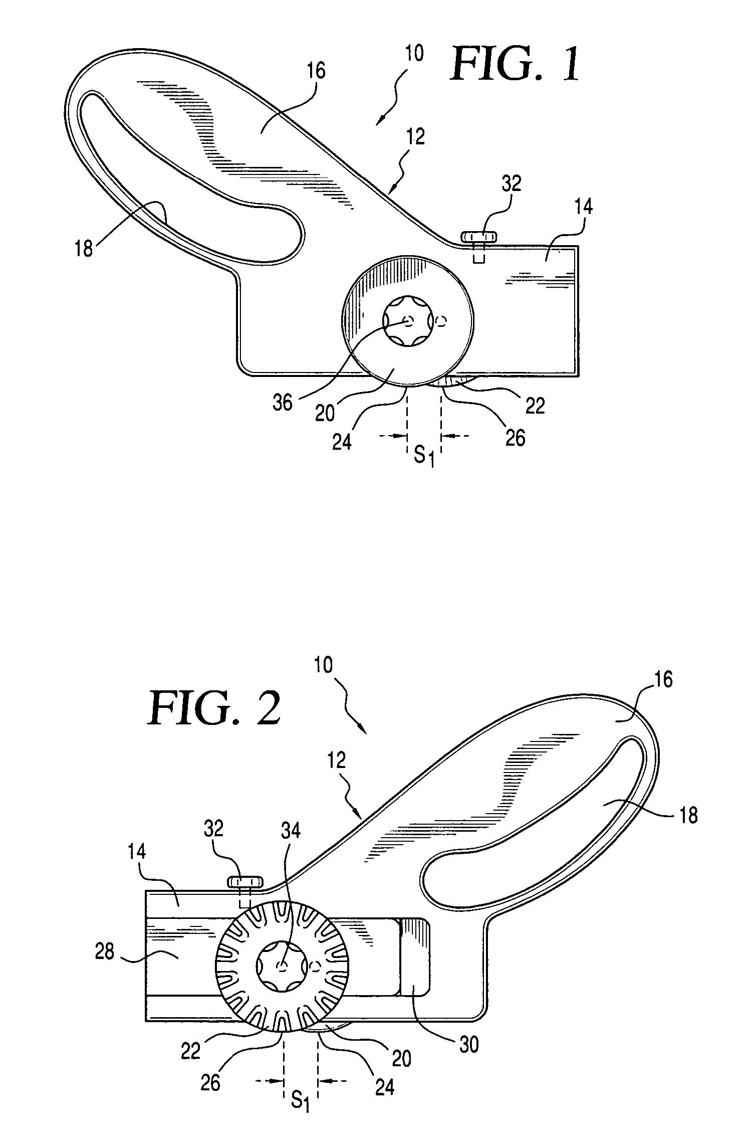
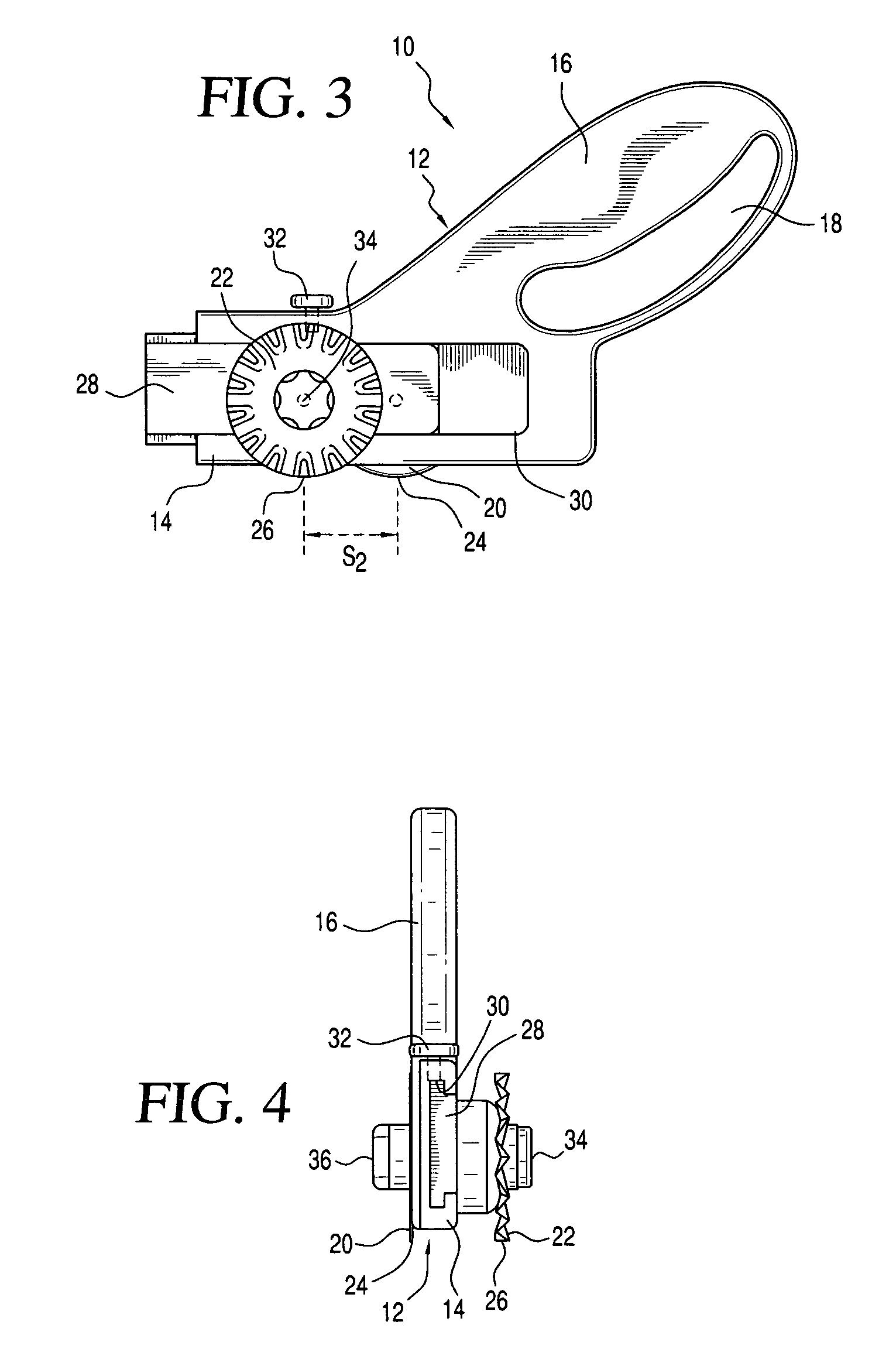
[0083]Referring to the accompanying drawings wherein like reference numbers refer to the same or similar elements, a cutting device 10 in accordance with the invention is shown in FIGS. 1-4 and generally provides for variable longitudinal spacing between two cutting blades, i.e., the position of one cutting blade in the longitudinal direction of the cutting device is adjustable relative to the position of the other cutting blade.

[0084]Cutting device 10 includes an elongate body 12 having a blade-mounting portion 14 and a handle portion 16 extending from the blade-mounting portion 14. Handle portion 16 includes a finger-receiving aperture18 into which one or more fingers of the user are placed to enable the user to grip the handle portion 16 and effectively use the cutting device 10. Handle portion 16 may be contoured to fit within the palm of the user's hand.

[0085]A pair of substantially parallel cutting blades 20, 22 are rotatably mounted on opposite sides of the blade-mounting por...

second embodiment

[0094]a cutting device 40 in accordance with the invention is shown in FIGS. 5-10 and generally provides for both variable longitudinal spacing between two cutting blades and variable transverse spacing the two cutting blades, i.e., the position of one cutting blade in a transverse direction of the cutting device is adjustable relative to the position of the other cutting blade. Variable transverse spacing involves the ability to adjust the cutting width defined as the transverse distance between the planes in which the cutting blades 42, 44 rotate. Cutting device 40 thereby enables the formation of strips of material having different widths. The form, orientation and shape of the cutting blades 42, 44 may be as described above with reference to cutting blades 20, 22.

[0095]Cutting device 40 includes an elongate body 46 having a blade-mounting portion 48 and a handle portion 50 extending from the blade-mounting portion 48. Handle portion 50 includes a finger-receiving aperture 52 int...
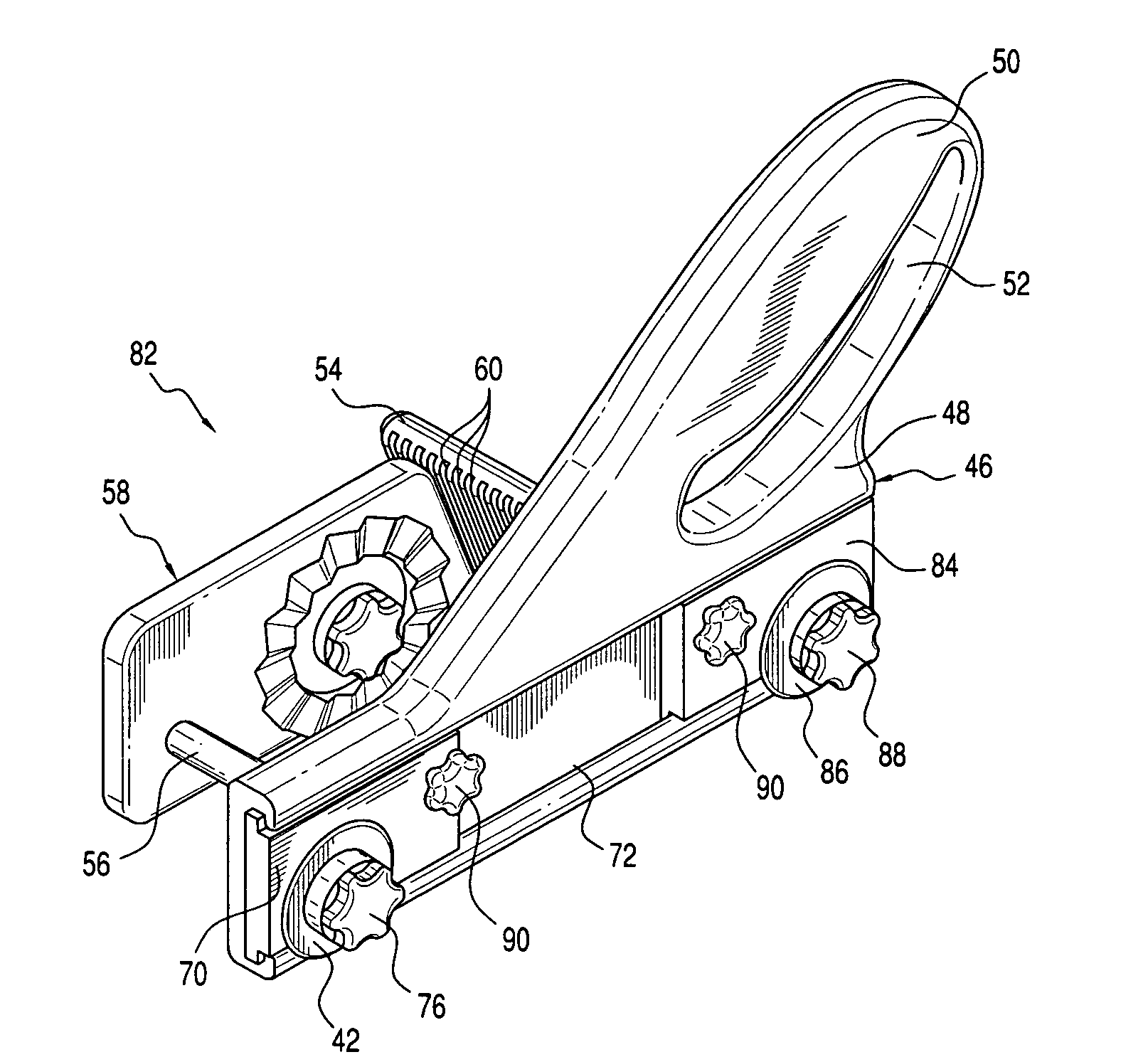
third embodiment

[0107]FIGS. 11-14 show a cutting device 82 in accordance with the invention which is similar to the one shown in FIGS. 5-10 except that longitudinal slot 72 is extended across the entire body 46, i.e., from one longitudinal end to the opposite longitudinal end, and an additional sliding member 84 is arranged in slot 72. A third cutting blade 86 is mounted on sliding member 84 via locking knob 88 and may be in substantially the same rotation plane as cutting blade 42 and thus also parallel to cutting blade 44. Alternatively, cutting blade 86 may be arranged in a rotation plane which intersects the rotation planes of cutting blade 42 and / or cutting blade 44.

[0108]Sliding members 70, 84 can be fixed in slot 72 by locking screws 90 arranged on the sliding members 70, 84 and passing therethrough into frictional contact with the body 46 when the sliding members 70, 84 are fixed in position. Contact between the locking screws 90 and the body 46 prevents movement of the sliding members 70, ...


PUM

PropertyMeasurementUnit
diameteraaaaaaaaaa
diameteraaaaaaaaaa
diameteraaaaaaaaaa

Abstract

Cutting devices including an elongate body having a handle and two rotatable cutting blades mounting on opposite sides of the body. One cutting blade is movable longitudinally relative to the other to enable variation in the longitudinal spacing between the cutting blades. In addition to or instead of the variable longitudinal spacing, one cutting blade is movable transversely relative to the other to enable variation in the transverse spacing between the cutting blades. Other cutting devices include a housing defining a blade-receiving cavity, an actuating mechanism pivotally mounted to the housing and a cutting assembly arranged in the cavity and including cutting blades. The cutting assembly is rotatable relative to the housing to selectively bring each cutting blade into a cutting position, and has a relaxed position in which the cutting blades are recessed within an outer periphery of the housing. The cutting assembly is biased into this relaxed position.

Description

CROSS REFERENCE TO RELATED APPLICATIONS[0001]This application claims priority under 35 U.S.C. § 119(e) of U.S. provisional patent application Ser. No. 60 / 619,248 filed Oct. 15, 2004 and U.S. provisional patent application Ser. No. 60 / 689,338 filed Jun. 10, 2005, both of which are incorporated by reference herein.FIELD OF THE INVENTION[0002]The present invention relates generally to cutting devices for cutting sheet material and in particular to cutting devices which are capable of simultaneously making multiple cuts in a substrate.[0003]The present invention also relates generally to fashioning devices which modify planar substrates into particular shapes and / or forms and / or provide them with designs and more particularly to fashioning devices which cut, scribe and / or emboss planar substrates in a spiral and / or circular manner. Thus, fashioning devices in accordance with the invention include cutting devices for cutting sheet material to make a single circular or spiral cut or simul...

Claims


Application Information

Patent Timeline
Patent Type & Authority Patents(United States)
IPC IPC(8): B26B21/00B26B1/00B26B3/00B26D11/00
CPCB26B25/005B26B29/02Y10T83/0215Y10T83/0222
Inventor STRAVITZ, DAVID M.
Owner STRAVITZ DAVID M
Why Eureka
Try Eureka