Defect inspection method and apparatus

a defect inspection and defect technology, applied in image enhancement, instruments, image data processing, etc., can solve the problems of large pixel level error, inconsistent information, and inability to ensure the coincidentity of two images to be compared, so as to achieve high reliability of inspection and effectively make defect review. , the effect of ensuring inconsistent information

Inactive Publication Date: 2006-02-23
HITACHI LTD
View PDF20 Cites 25 Cited by
  • Summary
  • Abstract
  • Description
  • Claims
  • Application Information

AI Technical Summary

Benefits of technology

[0012] Accordingly, it is an object of the invention to provide a pattern defect inspection method and apparatus with the above problems solved, and capable of examining by comparing patterns of different brightness so that defects can be inspected with high sensitivity and high reliability at all times.
[0018] Thus, according to the invention, the certainty of inconsistent information can be judged by using a scatter diagram of two detected images to be compared. In addition, since defects are detected by using information from the scatter diagram, the inspection can be made highly reliable. Moreover, use of the scatter diagram makes it possible to decide an appropriate threshold. Also, by using the certainty of inconsistent information, it is possible to effectively make defect review.
[0019] Therefore, reliable inspection data can be used by adding reliability. Furthermore, defects can be detected with high sensitivity without reducing the total inspection sensitivity by the brightness difference due to the change of the film thickness of a multilayer pattern. Therefore, in the manufacturing process of semiconductor devices, defects of patterns of a wafer after CMP can be detected with high precision and high reliability.

Problems solved by technology

In this pattern, the film thickness locally changes, easily causing irregular brightness.
However, because the pattern after CMP has sometimes a great change in brightness, there is a limit.
This method, however, does not assure that the two images to be compared are coincident.
Thus there is a great error in terms of pixel level contrary to the resolution of pixel or below.
Thus, applying a paraboloid to the sum of the squares of the differences and calculating the position where the minimum value is obtained must be said to be means having very large error.

Method used


Image

  • Defect inspection method and apparatus
  • Defect inspection method and apparatus
  • Defect inspection method and apparatus

Examples


embodiment 1

[Embodiment 1]

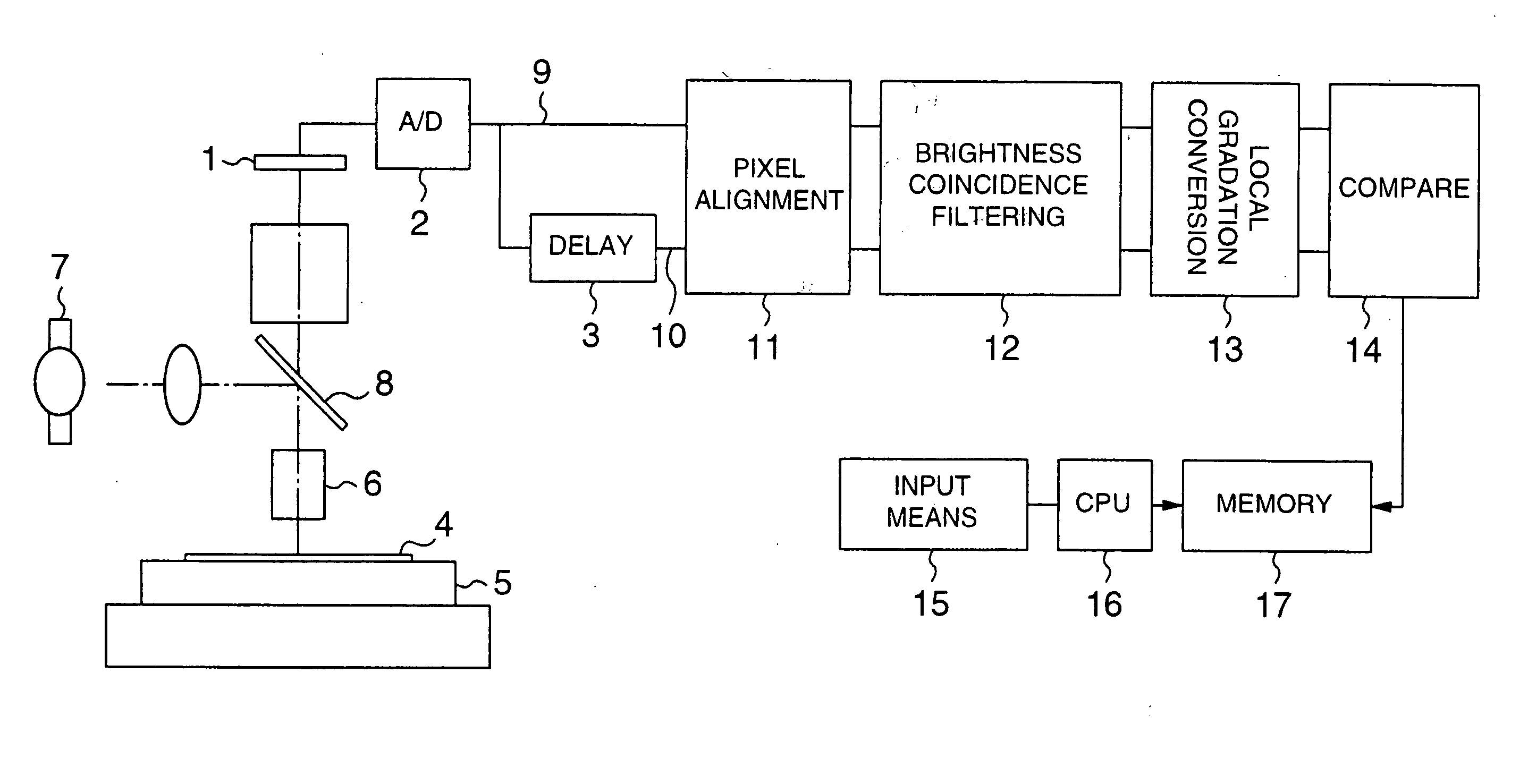
[0052]FIGS. 7 and 8 are block diagrams of pattern defect inspection apparatus according to the first embodiment of the invention.

[0053] It is assumed that this embodiment inspects, for example, patterns of a semiconductor wafer.

[0054] Referring to FIGS. 7 and 8, there are shown an image sensor 1 that responds to the brightness or gradation of light reflected from a semiconductor wafer 4 of patterns being inspected to produce a gradation image signal, an A / D converter 2 for converting the gradation image signal from the image sensor 1 into a digital image signal 9, a delay memory 3 for delaying the gradation image signal, and the semiconductor wafer 4 having patterns being inspected. There are also shown a stage 5 that is moved in X-direction, Y-direction, Z-direction and θ-direction (rotation) with the semi-conductor wafer 4 placed thereon, an object lens 6 facing the semiconductor wafer 4, a light source 7 for illuminating the semiconductor wafer 4 of the patterns b...

embodiment 2

[Embodiment 2]

[0123]FIG. 24 shows the second embodiment of a pattern inspection method and apparatus according to the invention. In this embodiment, an electron beam is used to scan the sample and the electrons generated from the wafer by the irradiation of the electron beam are detected. An electron beam image of the scanned region is thus obtained on the basis of the change of the intensity, and used to make a pattern inspection. The second embodiment overcomes the problems to be solved by the invention by setting a defect decision threshold for each pixel considering pattern shift and different gradations.

[0124] This system includes a detection unit 101, an image extractor 102, an image processor 103, a whole controller 104 for controlling the whole system.

[0125] The detection unit 101 will be described first.

[0126] Referring to FIG. 24, an electron beam emitted from an electron gun 31 passes through a magnetic field lens 32 and an object lens 33 and focused on the sample surf...

embodiment 3

[Embodiment 3]

[0148]FIG. 26 shows the third embodiment of a pattern defect inspection method and apparatus according to the invention. Referring to FIG. 26, in which like elements corresponding to those in FIGS. 7 and 8 are provided, there are shown the image sensor 1 for producing a gradation image signal according to the brightness, or gradation of the reflected light from the semiconductor wafer 4 that has patterns being inspected, the A / D converter 2 for converting the gradation image signal from the image sensor 1 into the digital image signal 9, the delay memory 3 for delaying the gradation image signal, the semiconductor wafer 4 having the patterns being inspected, and the stage 5 on which the semiconductor wafer 4 of the patterns being inspected is placed and which is moved in the X-direction, Y-direction, Z-direction and θ-direction (rotation). In addition, there are shown the object lens 6 placed facing to the semiconductor wafer 4, the light source 7 for illuminating the ...


PUM

PropertyMeasurementUnit
distanceaaaaaaaaaa
brightnessaaaaaaaaaa
defect inspectionaaaaaaaaaa

Abstract

A method of inspecting defects of a plurality of patterns that are formed on a substrate to have naturally the same shape. According to this method, in order to detect very small defects of the patterns with high sensitivity without being affected by irregular brightness due to the thickness difference between the patterns formed on a semiconductor wafer, a first pattern being inspected is detected to produce a first image of the first pattern, the first image is stored, a second pattern being inspected is detected to produce a second image of said second pattern, the stored first image and the second image are matched in brightness, and the brightness-matched first and second images are compared with each other so that the patterns can be inspected.

Description

CROSS REFERENCE TO RELATED APPLICATIONS [0001] This application is a continuation application of application Ser. No. 09 / 294,137, filed Apr. 20, 1999, based on Japanese Patent Application No. 10-110383, filed in Japan on Apr. 21, 1998 and No. 10-264275, filed Sep. 18, 1998, the contents of all of which are incorporated herein by reference in their entirety.BACKGROUND OF THE INVENTION [0002] The present invention relates to exterior inspection for detecting defects of patterns being examined, and particularly to a defect inspection method and apparatus for inspecting patterns in a semiconductor wafer or liquid crystal display. [0003] In a conventional inspection apparatus of this kind, as disclosed in JP-A-55-74409, an image sensor such as a line sensor is used to detect the image of a pattern being examined while the pattern is being moved, and the detected image signal is compared in its gradation with another image signal delayed by a predetermined time, so that the inconsistency ...

Claims


Application Information

Patent Timeline
Patent Type & Authority Applications(United States)
IPC IPC(8): G01N21/88G01N21/95G01N21/956G06K9/00G06T7/00
CPCG01N21/9501G01N21/95607G06T2207/30148G06T7/001G06T7/0004
Inventor MAEDA, SHUNJIOKA, KENJISHIBATA, YUKIHIROYOSHIDA, MINORUSHISHIDO, CHIETAKAGI, YUJIYOSHIDA, ATSUSHIYAMAGUCHI, KAZUO
Owner HITACHI LTD
Why Eureka
Try Eureka