In-vehicle relay device, in-vehicle monitoring device, in-vehicle network system, communication monitoring method, and recording medium

Active Publication Date: 2020-05-07
PANASONIC INTELLECTUAL PROPERTY CORP OF AMERICA
View PDF0 Cites 15 Cited by
  • Summary
  • Abstract
  • Description
  • Claims
  • Application Information

AI Technical Summary

Benefits of technology

[0006]According to the in-vehicle relay device or the like of

Problems solved by technology

The sophistication of electronic control technology for automobiles and the widespread use of connection of i

Method used


Image

  • In-vehicle relay device, in-vehicle monitoring device, in-vehicle network system, communication monitoring method, and recording medium
  • In-vehicle relay device, in-vehicle monitoring device, in-vehicle network system, communication monitoring method, and recording medium
  • In-vehicle relay device, in-vehicle monitoring device, in-vehicle network system, communication monitoring method, and recording medium

Examples


Example

First Embodiment

[0078]An example of anomaly determination made on control data by the in-vehicle network system 102 is described below.

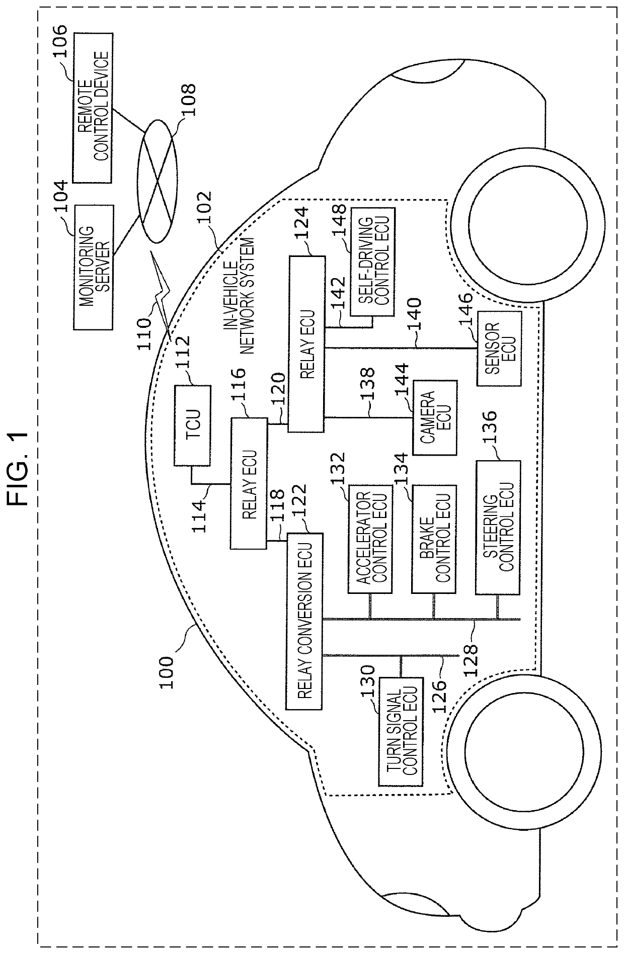
[0079]The anomaly determination is made on control data that includes a control command and that is transmitted from the Ethernet network to the control ECU in the CAN network. The transmission source of the control data is the remote control device 106. The control data is included in an Ethernet frame and is transmitted. The control data anomaly determination is made by the relay ECU 116.

[0080]In the following description of a determination as to an anomaly, the case where the relay ECU 116 makes a determination as to an anomaly of the control data transmitted from the self-driving control ECU 148 or the remote control device 106 is discussed as an example.

[0081]An example of a situation in which control data destined for a control ECU in a CAN network is transmitted from the self-driving control ECU 148 or the remote control device 106 is describe...

Example

Second Embodiment

[0115]Like the first embodiment, the second embodiment is described with reference to an example of anomaly determination made by the in-vehicle network system 102 illustrated in FIG. 1. In the following description, differences from the first embodiment are mainly described, and description of the constituent elements and the processing procedure the same as those of the first embodiment is briefly given as needed.

[0116]According to the present embodiment, among the processing procedures for determination of an anomaly of control data made by the relay ECU 116 according to the first embodiment, the process performed in the case of “YES” in step S508, that is, the process performed in the case where a match is found as the result of the matching process using the control command combination list is modified. This is only a difference from the first embodiment. FIG. 9 is a flowchart illustrating an example of the procedure for the operation performed by the relay ECU...


PUM


Abstract

An in-vehicle relay device prevents an anomaly of a control command exchanged over networks having different transmittable data sizes in a frame. The in-vehicle relay device relays communication between multiple control devices in a vehicle over the networks to which the control devices are connected. The in-vehicle relay device receives control data from a first control network. The control data includes, in a frame, a plurality of control commands to be executed by at least one of the control devices. The in-vehicle relay device determines, as a first determination, whether types of the control commands included in the frame form a first combination that is preset as a combination of control commands that are executable simultaneously. The in-vehicle relay device thereafter determines, as a second determination, whether the control data is anomalous by using the result of the first determination, and outputs the result of the second determination.

Description

BACKGROUND1. Technical Field[0001]The present disclosure relates to a relay device or the like that relays communication between a plurality of control networks in an in-vehicle network.2. Description of the Related Art[0002]The sophistication of electronic control technology for automobiles and the widespread use of connection of in-vehicle devices with a communication network give rise to the security risk to information for automobiles. Accordingly, the countermeasure technology is required. For example, CAN (Controller Area Network) standards have been employed for backbone networks of automobiles. Existing security countermeasure technologies for the in-vehicle network of the CAN include a technique for detecting anomaly by receiving periodically sent data frames and matching the transmission period against a predetermined rule regarding a transmission period (refer to, for example, International Publication WO 2015 / 170451).[0003]Recently, the sophistication of connection with ...

Claims


Application Information

Patent Timeline
IPC IPC(8): H04L12/40H04L12/46H04W4/40H04L29/06H04W88/16H04W92/02
CPCH04L12/4625H04L2012/40215H04L12/40013H04W88/16H04L12/4633H04L12/40182H04W92/02H04L2012/40273H04L69/08H04W4/40H04L12/28H04L12/46G07C5/008H04L67/12H04L67/025H04L67/565H04L67/535H04L69/085
Inventor TORISAKI, YUISHITERAZAWA, HIROYASUHAGA, TOMOYUKIUJIIE, YOSHIHIROKATO, RYO
Owner PANASONIC INTELLECTUAL PROPERTY CORP OF AMERICA
Why Eureka
Try Eureka