Optical transmission system

a transmission system and optical transmission technology, applied in the field of optical transmission systems, can solve problems such as insufficient conventional construction

Inactive Publication Date: 2002-04-23
KDDI CORP
View PDF1 Cites 21 Cited by
  • Summary
  • Abstract
  • Description
  • Claims
  • Application Information

AI Technical Summary

Benefits of technology

It is therefore an object of the invention to provide an optical transmission system satisfying such requirements and having signal transmission lines to branch stations which are durable against troubles.
Thus, by using double communication lines to each branch station, the communication path with the branch station is made more reliable.
A power supply line may be provided for each branching cable to prevent generation and entry of noise light.
Each branching unit may be made by using optical elements having no movable portion, such as demultiplexing means, multiplexing means, coupler, optical circulator, and so forth, to construct a highly reliable branching unit with less troubles and to realize a highly reliable optical transmission system.
On the other hand, the transmission loss can be reduced by using a selective switch.
When each optical transmission line of each inter-unit connecting cable is used in a unidirectional mode, branching units can be disposed more distant, and the probability of simultaneous damages to a plurality of branching cables can be decreased.

Problems solved by technology

A problem lies in that any trouble in the branching cable 24 or 26 disables transmission to and from a corresponding branch station 20c or 20d.
However, the importance of the branch stations 20c, 20d increases, the conventional construction is insufficient.

Method used


Image

  • Optical transmission system
  • Optical transmission system
  • Optical transmission system

Examples


first embodiment

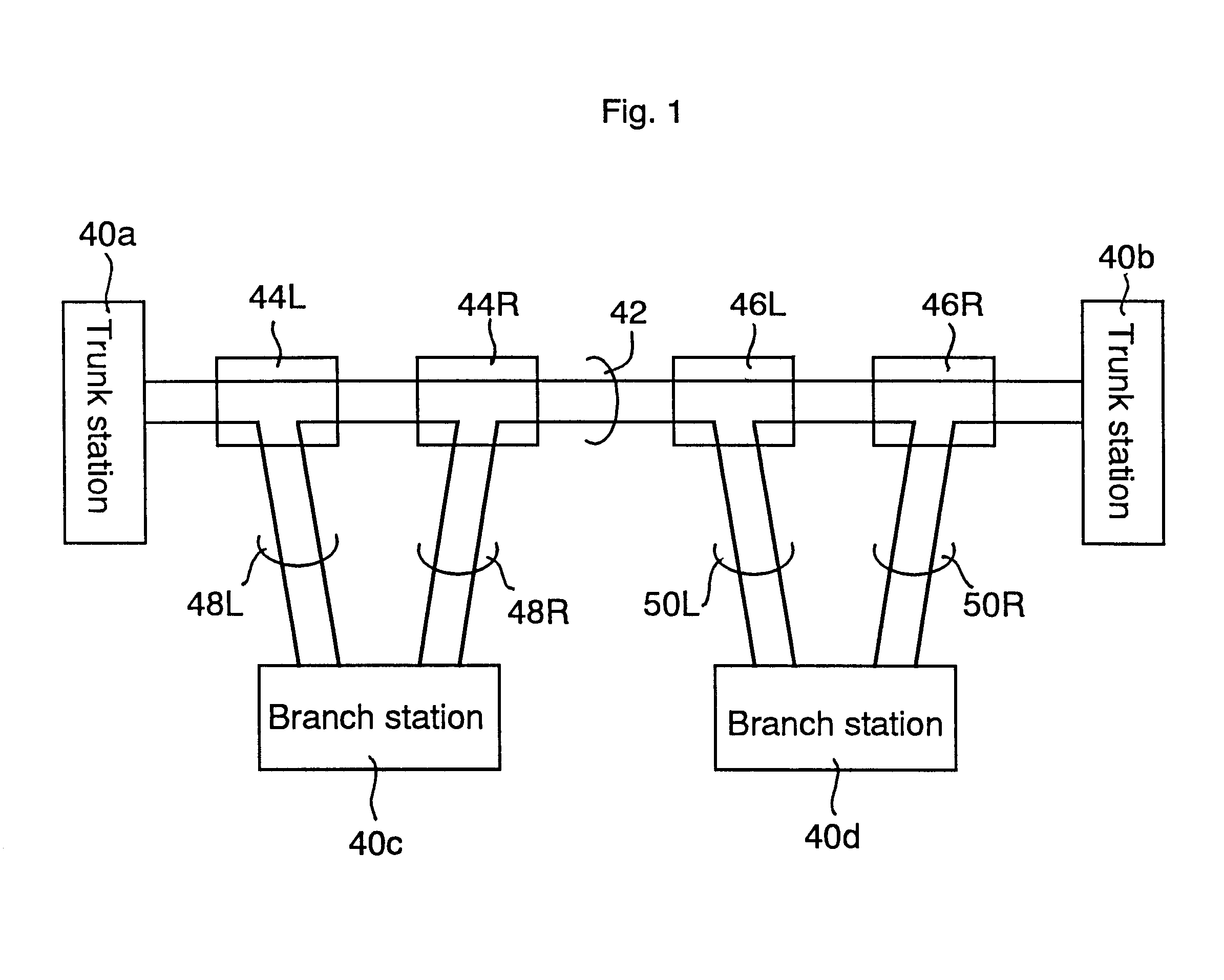
FIG. 1 schematically shows the invention. A trunk cable 42 having two pairs of optical fibers is provided between trunk stations 40a, 40b. One of two pairs of the optical fibers is used for communication between the trunk stations 40a, 40b. The other of two pairs of the optical fibers is used for communication among the trunk stations 40a, 40b and branch stations 40c, 40d. Two branching units 44L, 44R; 46L, 46R are provided on the other pair for each branch station 40c, 40d, and are connected to the associated branch stations 40c, 40d by branching cables 48L, 48R, 50L, 50R.

That is, the branch station 40c is connected to the branching unit 44L by the branching cable 48L having two optical fiber pairs and to the branching unit 44R by the branching cable 48R having two optical fiber pairs. Depending on cases, two optical fiber pairs are used to connect the branching units 44L and 44R, or three (or more) optical fiber pairs are required. That will be explained later in greater detail.

Th...

second embodiment

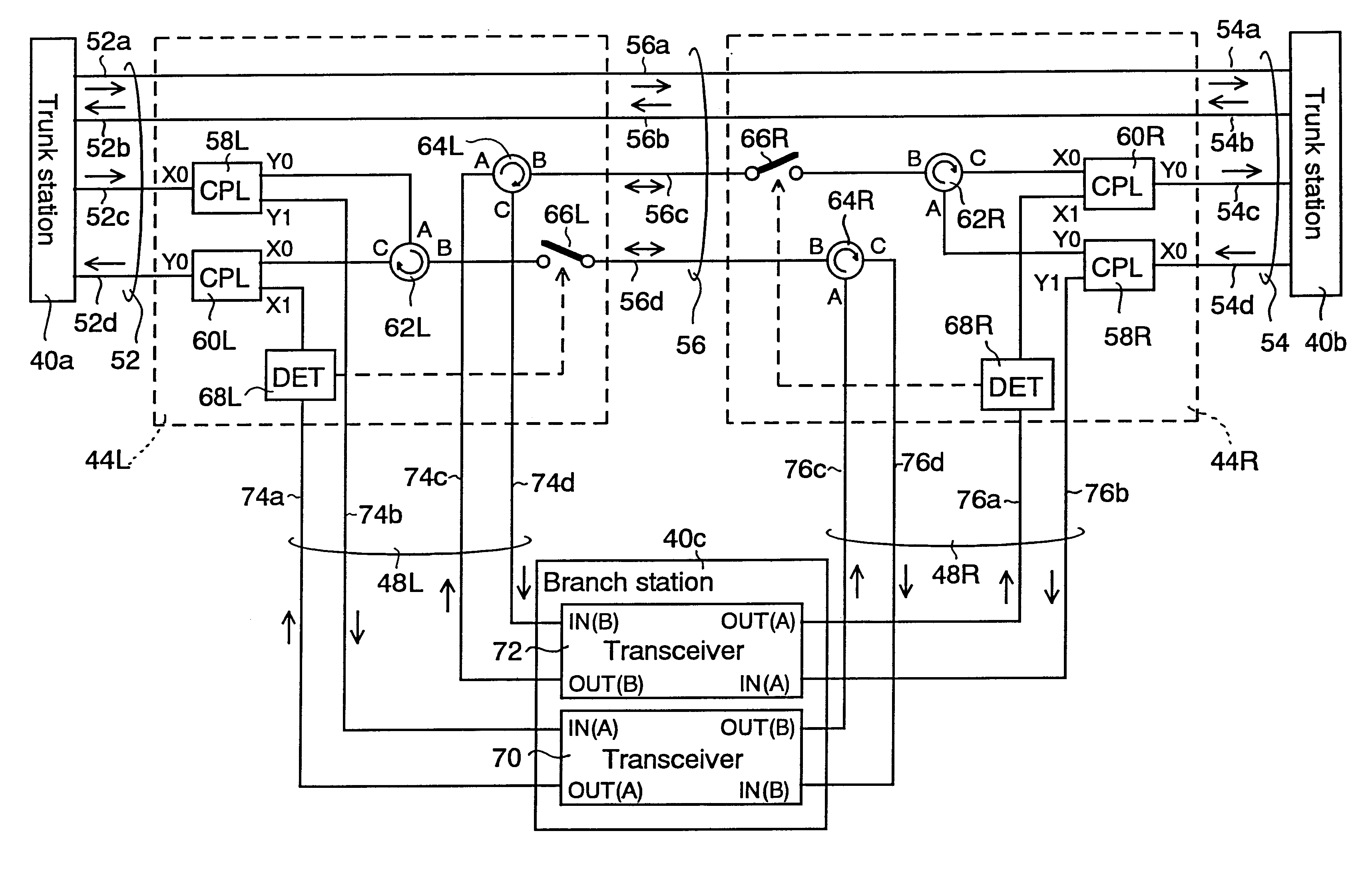
the branching units 44L and 44R corresponding to FIG. 3(a) is explained below. FIG. 14 is a block diagram of its construction. Similarly to FIG. 4 et seq., the branching units 46L, 46R and the branch station 40d are omitted from illustration for easier understanding, and common elements to those of FIG. 4 are labeled with common reference numerals. Similarly to the embodiments explained with reference to FIGS. 11 to 13, optical signals may propagate in opposite directions in the normal condition (when normal lines are used) and in a troubled condition (when spare lines are used), and optical amplifying repeaters of an ordinary type cannot be inserted in the optical fibers 56c and 56d of the inter-unit connecting cable 56. However, optical amplifying repeaters of a bidirectional type can be inserted.

Each of the branching units 44L, 44R has an optical coupler (or optical divider) 102L, 102R having one input port X0 and two output ports Y0, Y1 to divide input light through the input po...

third embodiment

the branching units 44L, 44R corresponding to FIG. 3(a) is explained below. FIG. 17 is a block diagram schematically showing its construction. As shown in FIG. 17, here are used optical circulators 110L, 110R, 112L, 112R each having three ports A, B, C instead of the optical couplers 106L, 106R, 108L, 108L used in the embodiment of FIG. 14. The optical circulators 110L, 110R, 112L, 112R are optical elements for outputting input light at the port A from the port B and for outputting input light at the port B from the port C.

In FIG. 17, common elements as those in the embodiment of FIG. 14 are labeled with common reference numerals. Similarly to the embodiment shown in FIG. 14, no optical amplifying repeater can be inserted in the optical fibers 56c and 56d of the inter-unit connecting cable 56 because optical signals may propagate in opposite directions in the normal condition (when normal lines are used) and in a troubled condition (when spare lines are used). The embodiment shown h...


PUM


Abstract

In an optical transmission, system, a trunk cable having two pairs of optical fibers is provided between first and second trunk stations to use one of the two pairs of the optical fibers for communication between the first and second trunk stations and the other for communication with first and second branch stations. Two branching units of first and second, and third and forth, are respectively provided for the first and second branch stations, and connected to each of the associated first and second branch stations, by first and second or third and forth branching cables. The first branch station connects to the first branching unit via the first branching cable having two pairs of optical fibers, and connects to the second branching unit via the second branching cable having two pairs of optical fibers. One of the two pairs of the optical fibers of the first branching cable and one of the two pairs of the optical fibers of the second branching cable are normally used, and the others are reserved as spare fibers. Alternatively, the first branching cable is normally used, and the second branching cable is reserved as a spare cable.

Description

FIELD OF THE INVENTIONThis invention relates to an optical transmission system and, more particularly, to an optical transmission system in which one or more branch stations are connected to a main optical transmission line.BACKGROUND OF THE INVENTIONThere are two different optical submarine cable systems for connecting branch stations to trunk lines, namely, the simple double landing system serially connecting main stations, and branch stations and the simple underwater branching system providing one branching apparatus for each branch station in a trunk line.FIG. 33 is a block diagram roughly sketching the general construction of the simple double landing system. Two trunk stations 10a, 10b and two branch stations 10c, 10d are provided. The trunk station 10a and the branch station 10c are connected by an optical fiber cable 12 having a pair of optical fiber lines (hereinafter called optical fibers), the branch station 10c and the branch station 10d are connected by an optical fibe...

Claims


Application Information

Patent Timeline
Patent Type & Authority Patents(United States)
IPC IPC(8): H04B10/213H04B10/032H04B10/071H04B10/27H04B10/29H04B10/40H04B10/03H04B10/50H04B10/60
CPCH04B10/278H04B10/27
Inventor KAWAZAWA, TOSHIOGOTO, KOJI
Owner KDDI CORP
Why Eureka
Try Eureka