
Method and apparatus for bit rate reduction in video telephony
a video telephony and bit rate reduction technology, applied in the field of video encoding, can solve the problem that streams still consume significant bandwidth
- Summary
- Abstract
- Description
- Claims
- Application Information
AI Technical Summary
Benefits of technology
Problems solved by technology
Method used
Image

Examples
Embodiment Construction
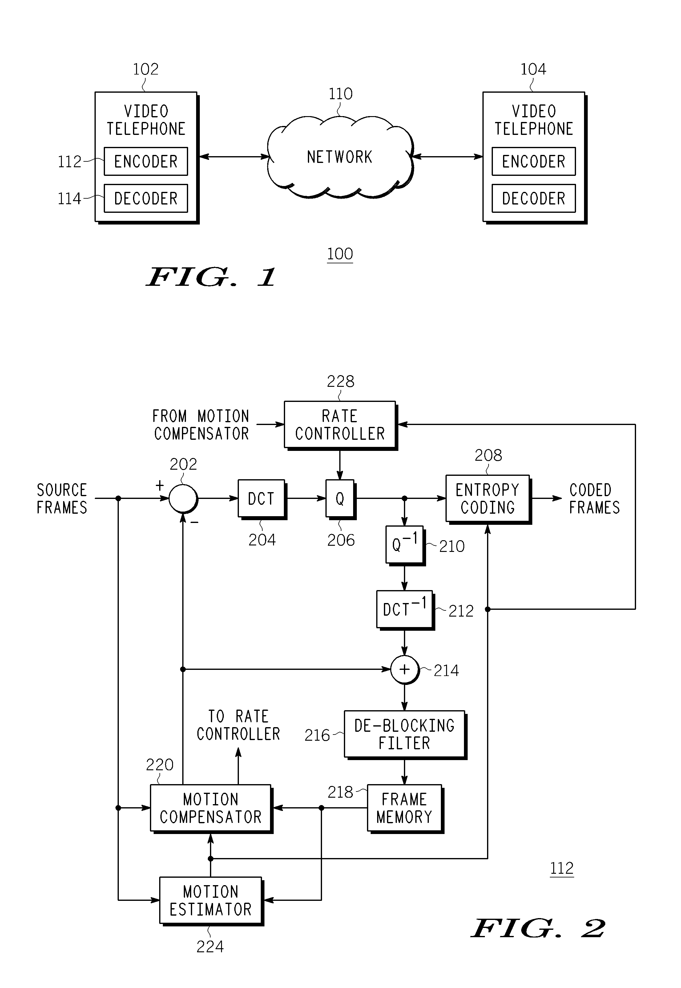
[0013]FIG. 1 is a block diagram depicting a general architectural overview of a video telephony network 100. The network 100 includes a video telephone 102 and a video telephone 104 connected by an internet protocol (IP) network 110. The video telephone 102 and the video telephone 104 may be any type of communication device capable of transmitting voice and video data via a wired or wireless connection to the IP network 110. Each of the video telephones 102 and 104 includes a video encoder 112 and a video decoder 114. The video encoder 112 is configured to encode input video from a video capture device (not shown) for transmission over the network 110. The video decoder 114 is configured to decode a coded video stream produced by the video encoder 112. Although only two video telephones are illustrated in FIG. 1, those skilled in the art will recognize that any number of video telephones may be coupled to the network 110.
[0014]FIG. 2 is a block diagram depicting an exemplary embodim...
PUM
 Abstract
Description
Claims
Application Information