Method for dispersion compensation regulation

a dispersion compensation and regulation method technology, applied in the direction of dispersion/dispersion elimination, fibre transmission, electrical equipment, etc., can solve the problems of inability to determine the bit error rate, the absolute magnitude compensation proves to be disadvantageous, and the error rate is virtually impossible to determine, so as to facilitate the setting up of optical transmission links and facilitate the setting up of optical transmission systems thereby being substantially simplified

Inactive Publication Date: 2006-07-11
XIEON NETWORKS SARL
View PDF2 Cites 5 Cited by
  • Summary
  • Abstract
  • Description
  • Claims
  • Application Information

AI Technical Summary

Benefits of technology

[0006]A key aspect of the method according to the present invention for dispersion compensation regulation is that in an optical transmission system, having dispersion compensation units, for transmitting high-bit-rate optical signals, in a first step a bit-rate-reduced optical signal is formed from the high-bit-rate optical signal by the N-fold repetition at the transmitting end of each logic 1 and each logic 0. In a second step, the bit-rate-reduced optical signal is transmitted, and in a third step the bit error rate of the transmitted bit-rate-reduced optical signal is determined at the receiving end. In a fourth step, the absolute-magnitude compensations of the dispersion compensation units are regulated in such a way that the determined bit error rate is minimized and, after the bit error rate has been minimized, the second to fourth steps are repeatedly carried out for the high-bit-rate optical signal. The inventive reduction of the transmission bit rate of the transmitting unit advantageously facilitates the setting up of the optical transmission link or the optical transmission system by virtue of the fact that even for a non-optimum estimation of the absolute-magnitude compensations of the dispersion compensation units it is possible in the optical receiving unit to recover the transmitted bit-rate-reduced optical signal without high technical outlay, and to determine the bit error rate of the transmitted optical signal, which is utilized as regulating criterion. Consequently, in the case of the first iteration of the method according to the present invention, the dispersion compensation regulation is firstly carried out for a low bit rate; for example, 10 Gbit / s. The transmission link precompensated in such a way is regulated in the next step for the actual transmission bit rate of the high-bit-rate optical signal such that the absolute-magnitude compensations required for an error-free bit error rate measurement are already set for dispersion compensation. The method according to the present invention can be indicated in a technically simple fashion as a control routine for driving the optical transmitter in already existing optical transmission systems, the setting up of an optical transmission system thereby being substantially simplified.

Problems solved by technology

However, the estimation of the absolute-magnitude compensations proves to be disadvantageous in the communication of high-bit-rate optical signals, since most estimated absolute-magnitude compensations lead to a bit error rate (BER) far removed from the minimum.
In this case, it is virtually impossible to determine the bit error rate, since the forward error correction (FEC) of the optical receiving unit is no longer capable of correcting such high bit errors.
Finding a suitable estimated value for the absolute-magnitude compensations is, therefore, extremely time-consuming and cost-intensive and does not always lead to an optimum dispersion compensation of the optical transmission links to be set up.

Method used


Image

  • Method for dispersion compensation regulation
  • Method for dispersion compensation regulation

Examples


Embodiment Construction

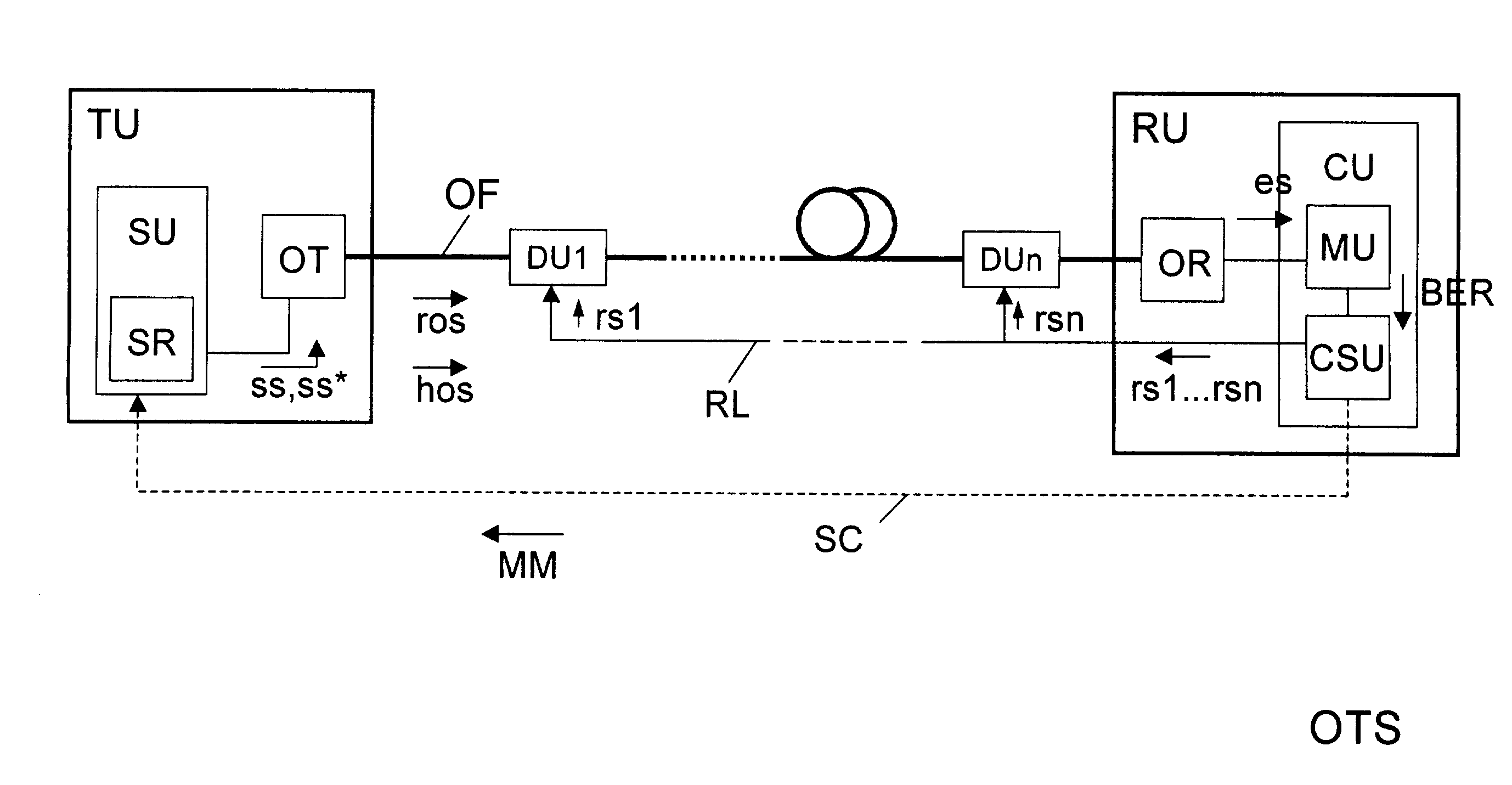
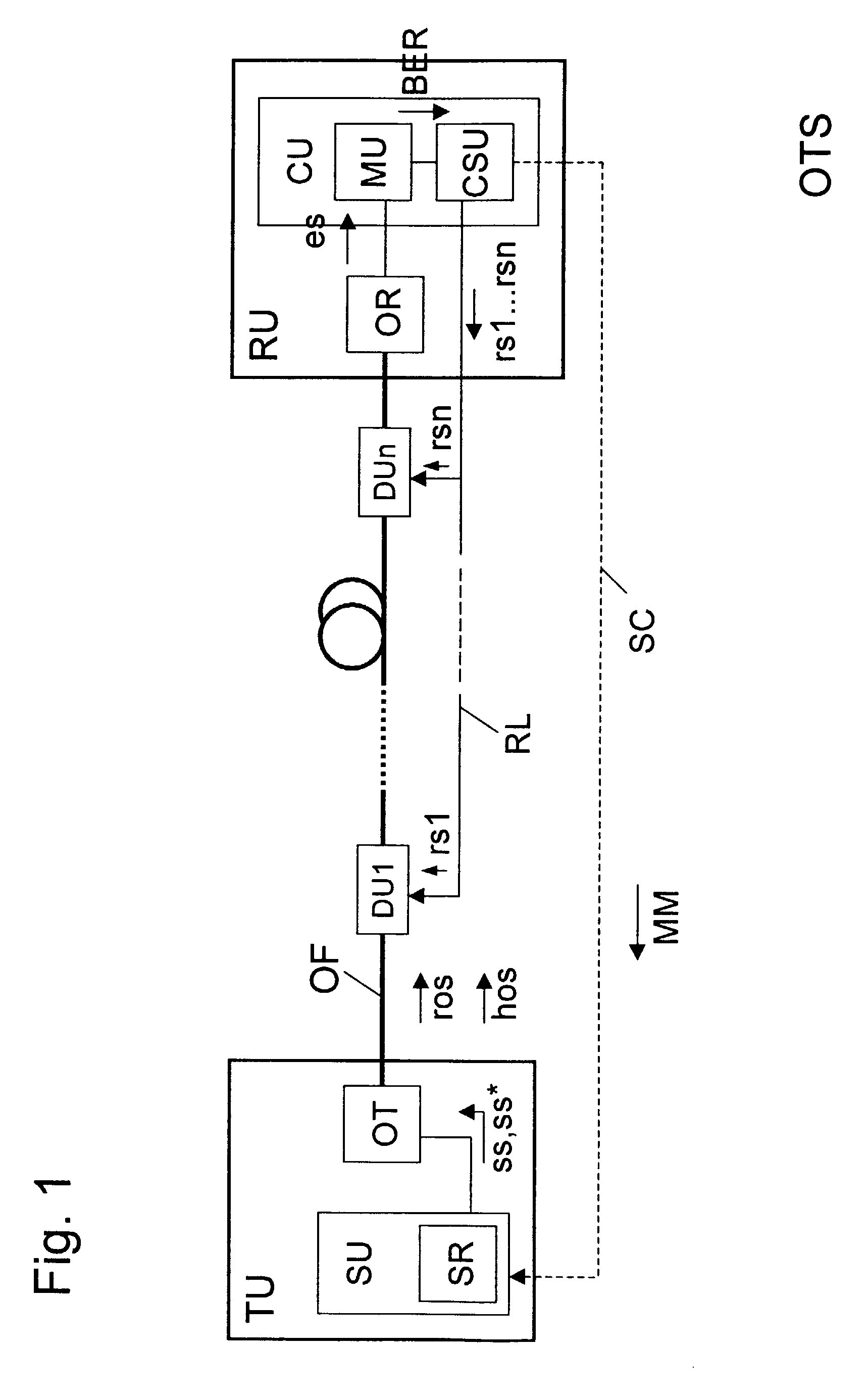
[0010]Illustrated by an example in FIG. 1 is an optical transmission system OTS that has an optical transmitting unit TU, an optical receiving unit RU, an optical transmission fiber OF, and first to nth optical controllable dispersion compensation units DU1 to DUn. The optical transmitting unit TU is connected to the optical receiving unit RU via the optical transmission fiber OF and the first to nth optical controllable dispersion compensation units DU1 to DUn.

[0011]Furthermore, the optical transmission unit TU has, for example, a control unit SU and an optical transmitter OT that is connected to the optical transmission fiber OF. A control routine SR via which the optical transmitter OT is controlled with the aid of control commands ss, ss* is executed in the control unit SU.

[0012]The optical receiving unit RU has an optical receiver OR and a regulating unit CU with a measuring unit MU and a control signal generating unit CSU. The input of the optical receiver OR is connected to t...


PUM


Abstract

A method for dispersion compensation regulation wherein, in order to transmit high-bit-rate optical signals, in a first step a bit-rate-reduced optical signal is formed from the high-bit-rate optical signal by the N-fold repetition at the transmitting end of each logic 1 and each logic 0, and in a second step the bit-rate-reduced optical signal is transmitted. In a third step the bit error rate of the transmitted bit-rate-reduced optical signal is determined at the receiving end, and in a fourth step the absolute-magnitude compensations of the dispersion compensation units are regulated in such a way that the determined bit error rate is minimized. After the bit error rate has been minimized by regulations the second to fourth steps are repeatedly carried out for the high-bit-rate optical signal.

Description

BACKGROUND OF THE INVENTION[0001]The present invention relates to a method for dispersion compensation regulation in an optical transmission system, having dispersion compensation units, for transmitting high-bit-rate optical signals.[0002]In the case of existing optical transmission systems, particularly optical wavelength division multiplexing (WDM) transmission systems, optical signals or WDM signals are transmitted at high bit rates (40 Gbit / s and more) via optical fiber link sections. During the transmission of optical signals, fiber dispersion caused by the different group delay times of the optical transmission fibers occurs, in particular, in addition to further nonlinear effects. The error-free transmission of optical signals via such an optical transmission system requires that this optical fiber dispersion be compensated with substantial accuracy. In this case, the tolerance range of an error compensation is directly proportional to the inverse square of the bit rate of t...

Claims


Application Information

Patent Timeline
Patent Type & Authority Patents(United States)
IPC IPC(8): H04B10/12H04B10/2513
CPCH04B10/25133
Inventor CREMER, CORNELIUS
Owner XIEON NETWORKS SARL
Why Eureka
Try Eureka