Image Processor, Image Processing Method, Recording Medium, Computer Program, And Semiconductor Device

a semiconductor device and image processing technology, applied in the field of image processing techniques, can solve problems such as complex initial settings and complicated initial settings, and achieve the effect of easy initial settings

Active Publication Date: 2007-12-06
MICRONAS
View PDF9 Cites 160 Cited by
  • Summary
  • Abstract
  • Description
  • Claims
  • Application Information

AI Technical Summary

Benefits of technology

[0023] As apparent from the aforementioned description, according to the present invention, initial settings can be made easily when a video image feature is used as an input interface.

Problems solved by technology

This often causes complicated and complex initial settings.
Insufficient settings or inappropriate position of the operator can result in production of the video image feature of the operator at a position not easily accessible to the object image or can cause misrecognition, all of which may be an obstacle to the correct and exact input operations.

Method used


Image

  • Image Processor, Image Processing Method, Recording Medium, Computer Program, And Semiconductor Device
  • Image Processor, Image Processing Method, Recording Medium, Computer Program, And Semiconductor Device
  • Image Processor, Image Processing Method, Recording Medium, Computer Program, And Semiconductor Device

Examples


example 1

[0069]FIG. 4 is a flow chart illustrating a procedure of the image processing method according to the present invention where the aforementioned image processing system is used.

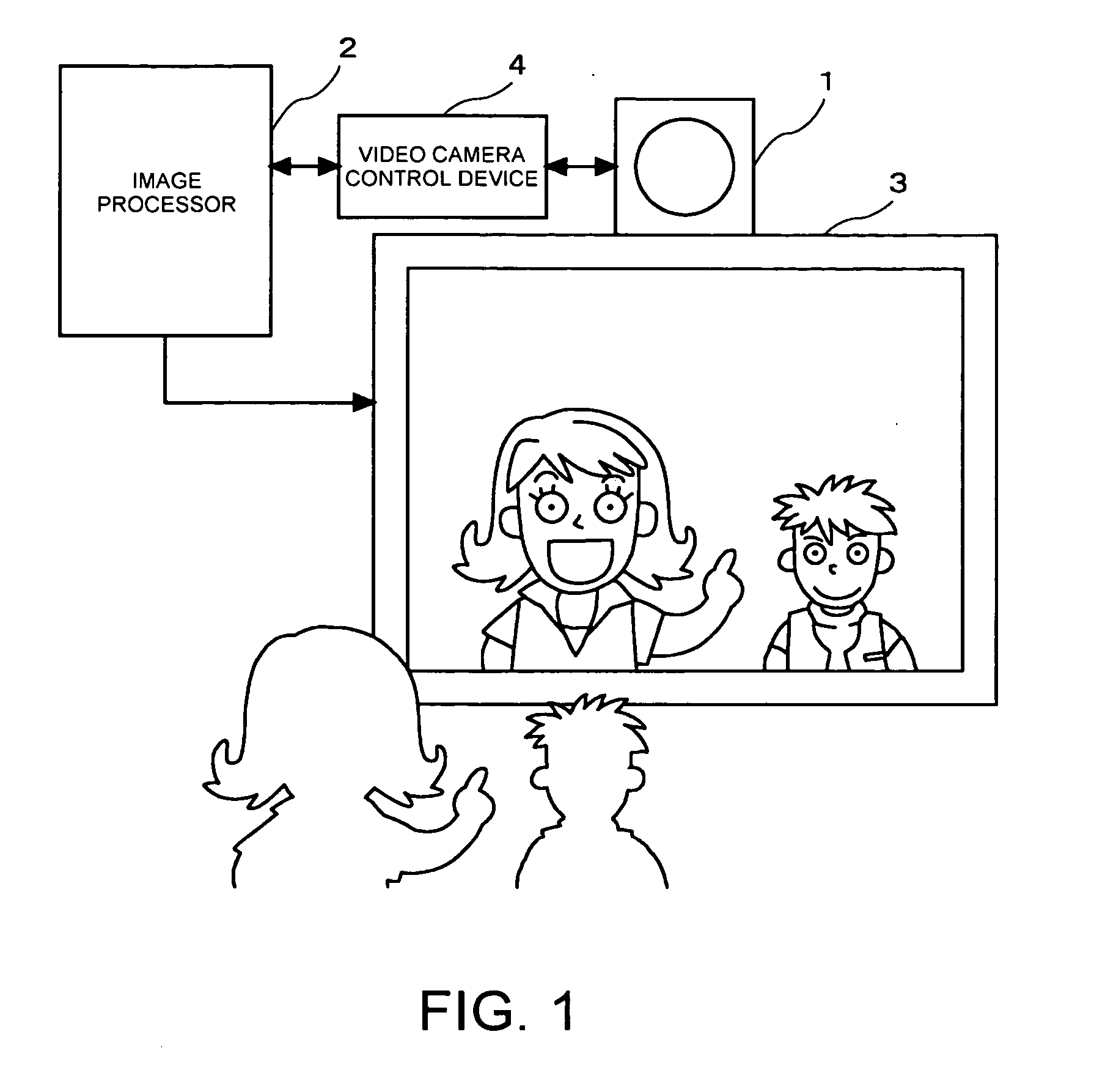
[0070] It is assumed that a mirrored video image feature including two candidate operators is produced on the display device 3, as shown in FIG. 1. For the purpose of clarifying the description, the number of the candidate operators produced on the display device 3 is two, but the number may be more, or only one. When there is only one candidate operator, he or she is specified as the operator.

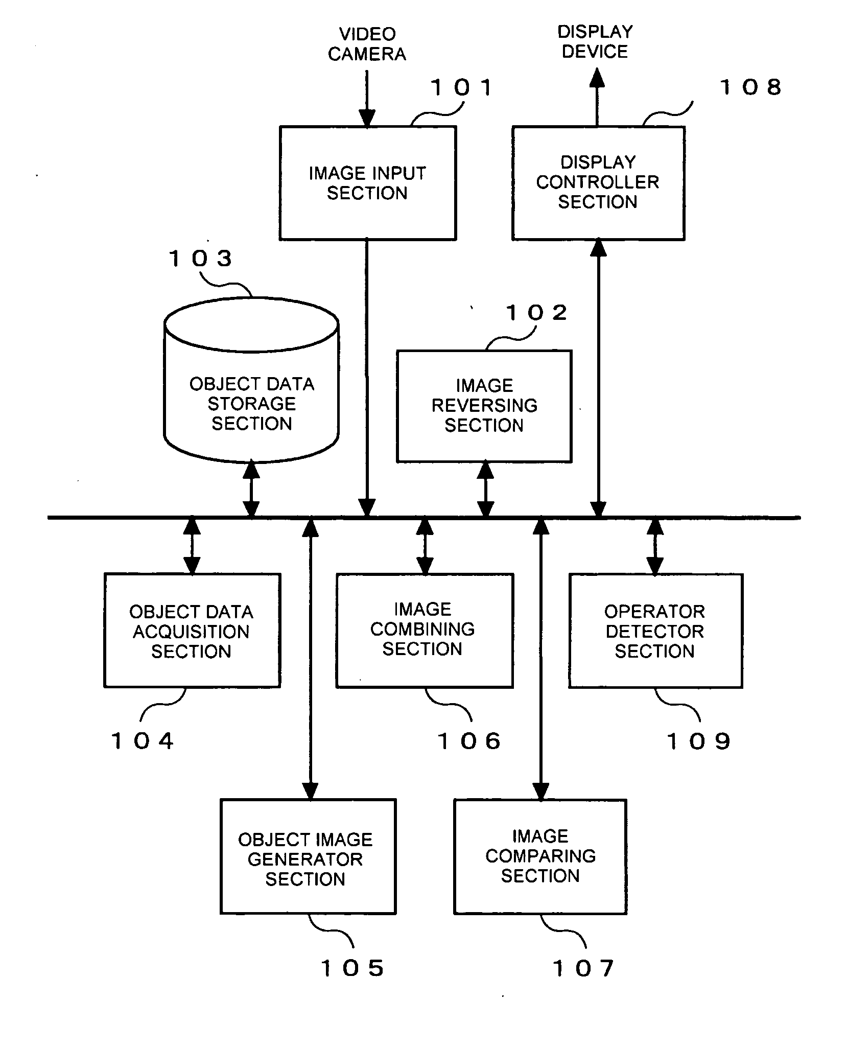
[0071] The mirrored video image feature is generated by supplying a video image feature captured by the video camera 1 to the image processor 2 and interchanging the right and left sides of the image by the image reversing section 102. The image of which right and left sides have been interchanged is produced on the display device, which results in the production of the mirrored video image feature as shown in FIG. 1....

example 2

[0084] In the Example 1, the candidate operator who accesses the menu image earlier is selected as the operator who actually performs the operation. However, the operator who actually performs operation may be selected by using a stereo-matching technique as described below. In the Example 2, two sets of mirrored video image features are provided by means of, for example, preparing two video cameras 1. FIGS. 12 and 13 are views showing an example of combined images in which a menu image is superimposed on top of two mirrored video image features.

[0085] Two mirrored video image features are, for example, stereo images for right and left eyes. In the example shown in FIGS. 12 and 13, FIG. 12 shows a right eye image component while FIG. 13 shows a left eye image component. The operator detector section 109 compares these two combined images and selects the candidate operator who is closer to the menu image as the operator. In the example shown in FIGS. 12 and 13, the candidate operato...


PUM


Abstract

To provide an image processing technique for easy initial settings when a video image feature is used as an input interface.
This is an image processor having an image combining section 106 for combining a mirrored video image feature that includes an image of an operator as a portion thereof and an object image of an object that is associated with a predetermined event, to generate a combined image, and being adapted to provide production of the combined image on a display device. This image processor has a detection section 109 for detecting the position of an image of an operator included in the mirrored video image feature. The image combining section 106 is adapted to combine the object image and the mirrored video image feature in such a manner that the object image is displayed in a range that an image of a hand of the operator can reach, depending on the position of the image of the operator detected by the detection section 109.

Description

TECHNICAL FIELD [0001] The present invention relates to an image processing technique with which captured images captured with an image capturing device such as a video camera are used as an input interface for commands for example. BACKGROUND OF THE INVENTION [0002] Keyboards, mouses, and controllers are examples of typical input devices for computers and video game machines. Operators enter a desired command that they want by using such an input device in order to work, for example, a computer so that it performs processing according to the command entered. The operators watch / listen, for example, images and sounds obtained as a result of the processing, through a display device or a speaker. Operators press many buttons on the input device and do other operations while looking at a cursor displayed on a display device, thereby to enter a command or commands. [0003] In recent years, some techniques have been developed that allow command input by using a video image feature capture...

Claims


Application Information

Patent Timeline
Patent Type & Authority Applications(United States)
IPC IPC(8): H04N7/01G06F13/14G06T1/00G06F3/00G06F3/01G06T3/00G06T7/00G06T7/20G06T7/254G06T7/60G06T7/66
CPCG06F3/012G06F3/0482G06F3/0481G06F3/017
Inventor OHBA, AKIOSUZUKIKAKE, TOMOKAZU
Owner MICRONAS
Why Eureka
Try Eureka