Fastening structure of signal connector

a technology of fastening structure and signal connector, which is applied in the direction of threaded fasteners, coupling device connections, screws, etc., can solve the problems of poor waterproof effect, poor signal receiving efficiency, and inefficiency and practicality of the fastening structure provided, and achieve stable and tight connection and simple structure

Inactive Publication Date: 2010-03-23
LANTEK ELECTRONICS
View PDF6 Cites 23 Cited by
  • Summary
  • Abstract
  • Description
  • Claims
  • Application Information

AI Technical Summary

Benefits of technology

[0009]One object of the present invention is to provide a fastening structure of signal connector having a stable and tight connection.
[0010]Another object of the present invention is to provide a fastening structure of signal connector which is simple in structure and an installation of a waterproof lining ring on the signal connector is not effected.

Problems solved by technology

A signal connector is a necessary unit for an electronic equipment for signal inputting / outputting, the electronic equipment, e.g. a coaxial cable distributor, or a multitap, or a splitter, a signal amplifier, or a direction coupler module having functions of signal distributing, coupling and amplifying, is often provided at outdoors, so rainwater often penetrates into the signal connector and this may cause poor signal receiving efficiency.
For providing a waterproof function, a waterproof lining ring (not shown) is often provided on the signal connector 10; because the whole portion of the signal connector 10 is provided with thread, the waterproof lining ring is not able to be tightly provided on the surface of the column member of the signal connector, a poor waterproof effect is therefore occurred.
But the signal connector 30 is fastened on the base seat 20 by the thread section 304 provided at the bottom portion of the signal connector 30, an operation of reverse rotation is capable of letting the signal connector 30 and the base seat 20 be separated from each other, therefore the fastening structure provided is not efficient and practical.
But the tightening status can be loosed via applying an external force, the signal connector 40 and the base seat 20 are separated, so the tightening fastening means provided is also not efficient and practical.

Method used


Image

  • Fastening structure of signal connector
  • Fastening structure of signal connector
  • Fastening structure of signal connector

Examples


Embodiment Construction

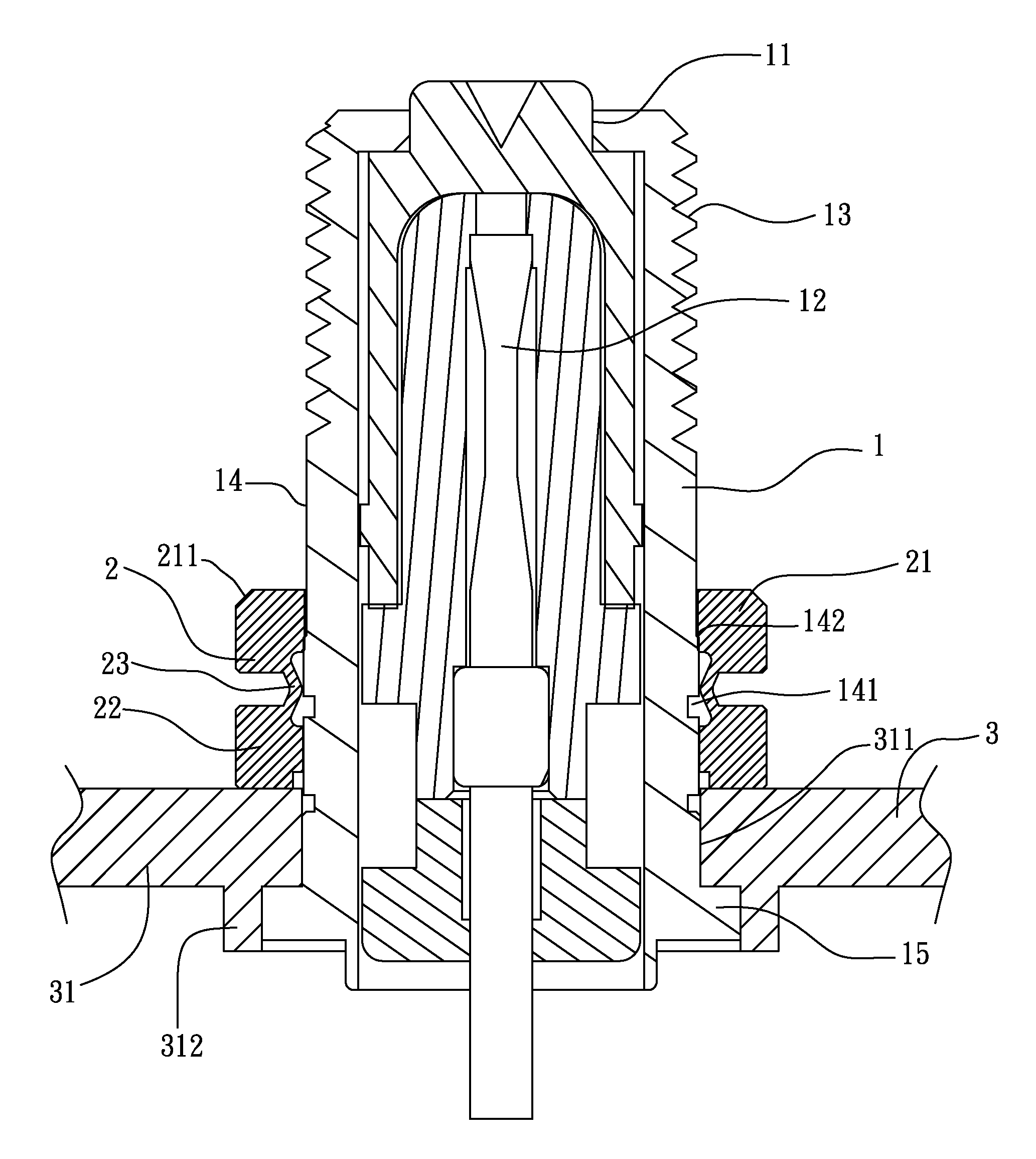
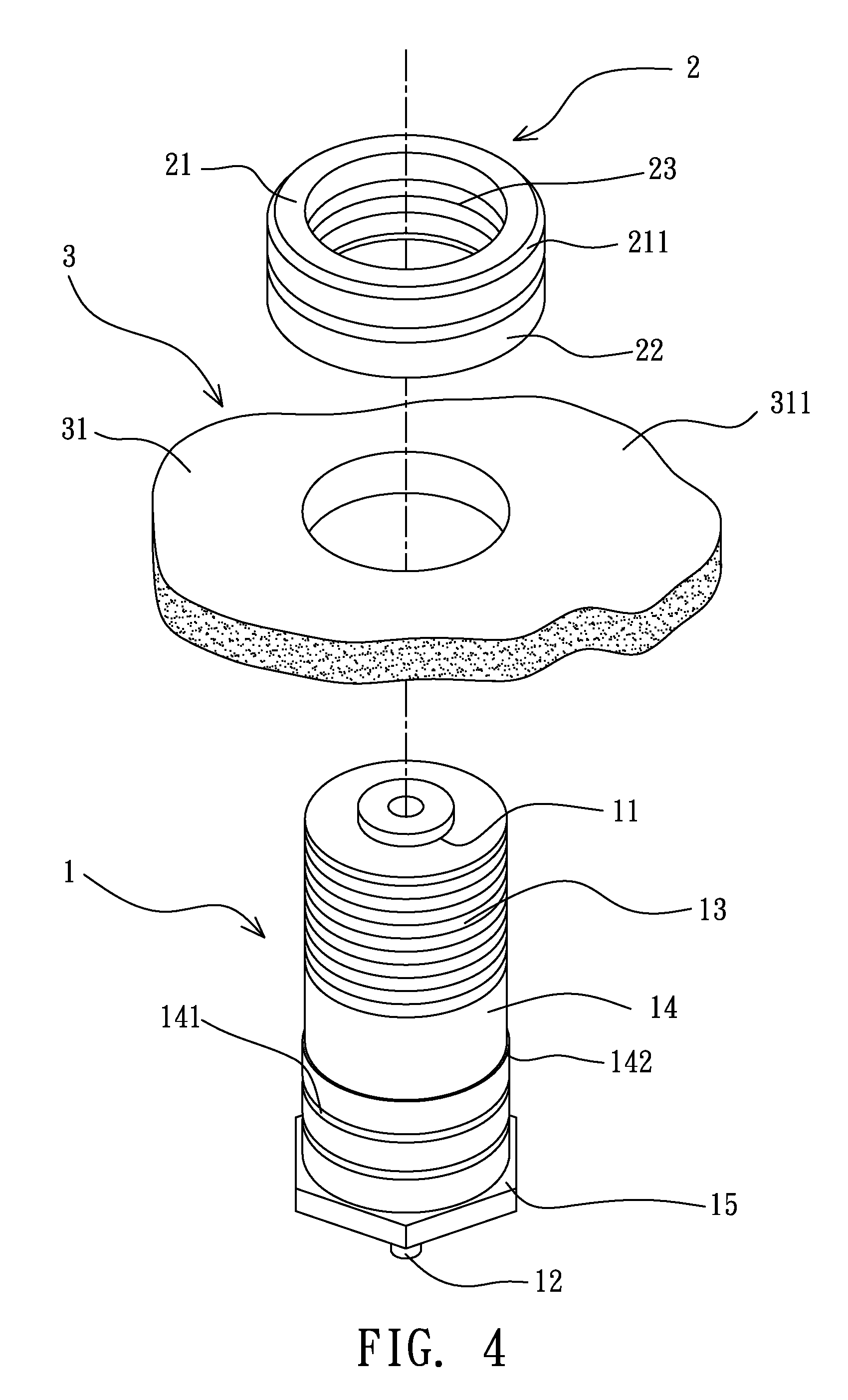
[0023]As shown in FIG. 4, the fastening structure of signal connector provided by the present invention is composed by a connector main body 1, a latching ring 2 and an electronic equipment 3.

[0024]The connector main body 1 is in a round-column shape, an insert orifice 11 is formed on a top end of the connector main body 1, and a signal terminal 12 (shown in the FIG. 5) is provided inside the connector main body 1, a top portion of the connector main body 1 has a thread section 13 for being connected to a joint of an end section of a coaxial cable so as to obtain an electrical connection. A middle portion of the connector main body 1 is provided with a combing ring-shaped surface 14, a positioning slot 141 is provided on the combing ring-shaped surface 14, the combining ring-shaped surface 14 is preferably designed to a stepped shape, so a flange 142 having a larger outer diameter is obtained and the positioning slot 141 is disposed below the flange 142.

[0025]For positioning the con...


PUM


Abstract

The present invention relates to a fastening structure of signal connector, comprises: a connector main body, which is a round-column shaped member, an insert orifice is provided on a top end of the connector main body and a signal terminal is provided in the connector main body, a middle portion of the connector main body has a combining ring-shaped surface, a positioning slot is provided on the combining ring-shaped surface, a bottom portion of the connector main body is provided with a positioning section; the connector main body is passed through a through hole preset on a base seat of an electronic equipment and the positioning section thereof is connected to a jointing section provided at a bottom end of the through hole; and a latching ring, an arched connecting sheet is provided between a top ring member and a bottom ring member for connection, and the latching ring is sleeved on the combining ring-shaped surface via the top end of the connector main body, so the bottom end of the bottom ring member is against the base seat and the connecting sheet is positioned in the positioning slot; when the top ring member is punched and downwardly moved, the connecting sheet is compressed and deformed and is latched in the positioning slot, so the connector main body is stably and tightly fastened on the base seat.

Description

BACKGROUND OF THE INVENTION[0001]1. Field of the Invention[0002]The present invention relates to a signal connector, more particularly to a fastening structure of signal connector.[0003]2. Description of Related Art[0004]A signal connector is a necessary unit for an electronic equipment for signal inputting / outputting, the electronic equipment, e.g. a coaxial cable distributor, or a multitap, or a splitter, a signal amplifier, or a direction coupler module having functions of signal distributing, coupling and amplifying, is often provided at outdoors, so rainwater often penetrates into the signal connector and this may cause poor signal receiving efficiency.[0005]As shown in FIG. 1, which is a schematic view of a signal connector of a conventional coaxial cable, the signal connector passes through a base seat, and the portion of the signal connector provided above the location where the base seat is provided has a thread section 101, so a nut 102 can be screw-fitted via the thread s...

Claims


Application Information

Patent Timeline
Patent Type & Authority Patents(United States)
IPC IPC(8): H01R13/73F16B19/00
CPCH01R13/74
Inventor LU, SHAN-JUI
Owner LANTEK ELECTRONICS
Why Eureka
Try Eureka