Method and system for drying out the leather side of a pelt stretched out and fixed in this position on a pelt board

a technology of leather side and pelt, which is applied in the direction of leather/skins/hides/pelt mechanical treatment, skin/hides/leather/fur manufacturing apparatus, leather/skins/hides/pelt mechanical treatment, etc., can solve the problem of destroying 2-3 cm of the pelt where this is widest, unable to achieve the optimum price of pelt at the fur auction, and damage to the pel

Active Publication Date: 2010-04-06
MINKPAPIR
View PDF5 Cites 18 Cited by
  • Summary
  • Abstract
  • Description
  • Claims
  • Application Information

AI Technical Summary

Benefits of technology

[0028]A further aspect of the invention is to make possible a more effective and quicker manner in which to effect the removal of the dried pelt from a pelt board after the drying process has been concluded.
[0123]All in all, with the method, and the system for the execution of the method as disclosed herein utilizing the pelt board according to the present invention, there is provided a new generation of distension elements / pelt boards for use with the drying process in the production of pelts, which at the same time solves the problems with the securing of the pelts stretched and secured in this position on the board during the drying procedure, without the use of securing means which penetrate and damage the pelts, an improvement of the drying of the leather side of the pelt, with the result that the dried pelts do not have “black spots” (areas not dried), and the possibility for a significant saving in the labour in connection with the removal of the dried pelts.

Problems solved by technology

After drying, the clips are removed and thereafter the pelt is removed from the pelt board, which is also often effected mechanically, and which as a consequence of the maximum stretching of the pelt often leaves elongated holes in the pelt from the clips, the result being that the optimum price can not be achieved for the pelts at the fur auction, in that 2-3 cm of the pelt where this is broadest is ruined.
Sometimes, the mechanical removal of the clips also gives rise to damages to the pelts.
The holes from the clips thus constitute great losses for the fur farmers, and furthermore considerably reduce the possibilities of use of the pelts when these are subsequently processed.
The use of said staples will result in holes in the pelt in the stapled areas, thus reducing the value of the pelts, which is undesirable.
Moreover, the use of the staples damages the wood of which the pelt board is made.
The work in connection with the dismounting (removal) of pelts stretched on pelt boards after the conclusion of the drying process is time-consuming, even though machines have been developed for the cutting-up of the fixing-bags, the extraction of the staples and the drawing-free of the pelt from the pelt board.
However, a disadvantage with the use of the pelt-bag is that it prevents the through-flow of air on the leather side of the pelt during the drying process, which can result in what is known in the fur trade as “black spots”, and herewith oxidisation of the leather side of the pelt.
The said black spots are places on the pelt where the leather side has not been adequately dried during the drying process, and where the pelt is very exposed to attack from mites, with the result that the hairs on the fur side of the pelt become loose and can fall out, with consequently reduced possibilities of use for the pelt, which is completely undesirable.
Moreover, pelts which have “black spots” can not be used in the production of fur products where the leather side of the pelt is turned outwards.
It is estimated that 25% of the pelts received at the fur auctions can not be used with the leather side outwards because of insufficient drying.

Method used


Image

  • Method and system for drying out the leather side of a pelt stretched out and fixed in this position on a pelt board
  • Method and system for drying out the leather side of a pelt stretched out and fixed in this position on a pelt board
  • Method and system for drying out the leather side of a pelt stretched out and fixed in this position on a pelt board

Examples


second embodiment

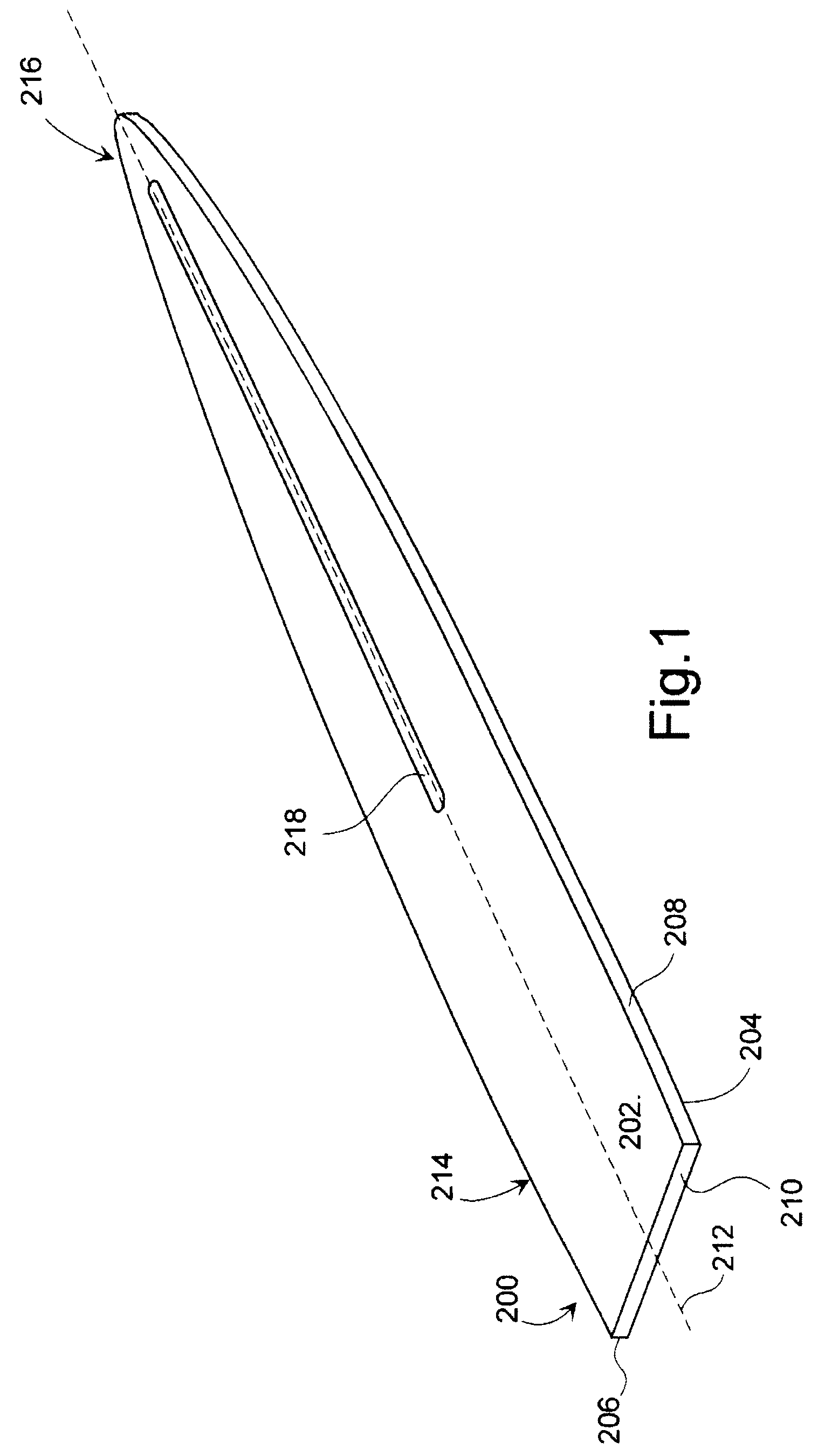
[0149]In FIG. 4 is shown the board 6. This has the same shape as the board shown in FIG. 3, but where the nature of the surface 12 as an open structure appears clearly as a consequence of the holes 10 in the board. In the shown embodiment, the surface 12 is provided with holes 10 between the front end 14 and to a distance in the area 15 of the board 6 near the foot end 16, where the extent of the board in the direction of the first transverse axis 12 and the second transverse axis 14 is more or less constant.

[0150]Already here it shall be mentioned that the inventor has realised that the holes 10 can assume another configuration or combination of that shown and other configurations. Moreover, in the area 15 of the board 6 near the foot end 16, where the extent of the board in the direction of the first transverse axis 12 and the second transverse axis 14 is more or less constant, the holes can be provided with edges which extend up over the surface 12. This will contribute towards a...

third embodiment

[0174]It shall further be mentioned that the board 6 can be configured with other embodiments of the surface 12. In FIG. 14 and FIG. 15 there is thus shown the pelt board according to the invention, where a part of the surface has a longitudinal grooving 29 with the grooves arranged substantially parallel with the longitudinal axis 18 of the board. The distension element / pelt board 6 shown in FIG. 14 and FIG. 15 further comprises in relation to the longitudinal grooving 29 second transverse grooving / serrations 31, the extent of which, as shown in FIG. 14 and FIG. 15, is limited to a part of the area 15 of the board 6 closest to the foot end 16, and at a distance from the foot end 16, where the extent of this in the direction of the first transverse axis 20 and the second transverse axis 22 is more or less constant, to and including a part of the area 33 where the extent of the board in relation to the longitudinal axis 18 in the direction of the first transverse axis 20 and the seco...

fourth embodiment

[0175]In FIG. 16 there is shown a further and fourth embodiment of the pelt board 6 according to the invention. As indicated in the figure, but which appears more clearly in FIG. 17 and FIG. 18, this comprises the longitudinal grooving 29 in the board's lower end in the area 15, and also a transverse corrugation 31 to provide a good counter-hold on the leather side of the pelt, which is pressed against the board 6 by a fixing-bag (not shown) while it is stretched and secured in this position during the drying process. As further appears clearly from FIG. 18, which is an exploded end view of the pelt board 6, seen from the foot end 16, the half shells 48, 50 extend in an arched manner in combination with the grooving 29.

[0176]In this embodiment, as shown most clearly in FIG. 16 and FIG. 17, and to some degree also in FIG. 21, in the half part of the board nearest the pointed end 14, the distension element / pelt board 6 comprises recesses 180, 182 extending in parallel in the half shel...


PUM

PropertyMeasurementUnit
humidityaaaaaaaaaa
temperatureaaaaaaaaaa
areaaaaaaaaaaa

Abstract

A method, a system and a pelt board for the drying of the leather side of pelts from furred animals, in which the pelt board is a hollow distension element, the surface of which has an open structure. The leather side is dried by changing the air within the distension element. The distension element is lockable in a position in which it has a first circumference, and can also assume a position or be force controlled to a position in which it has a circumference which is smaller than the first, which results in a considerably easier removal of the pelt from the pelt board. A quicker, more uniform and more effective drying of the pelts is achieved, so that “black spots” on the leather side are avoided, and the pelt is fixed in its stretched position on the pelt board without the use of clips / staples.

Description

BACKGROUND OF THE INVENTION[0001]1. Field of the Invention[0002]The present invention relates to a method for the drying of the leather side of a furred animal pelt which is stretched out and fixed in this position on a pelt board, and a system for the execution of the method.[0003]2. Description of Related Art[0004]The invention further relates to a distension element / pelt board which can be used with the system, and which in the following will for practical reasons be randomly referred to as a pelt board or distension element, where said pelt board has a longitudinal axis, a first transverse axis (breadth axis) and a second transverse axis (height axis), and front end for receiving the cranium end of the pelt, and a foot end which terminates preferably at right-angles in relation to the longitudinal axis of the pelt board.[0005]The invention also relates to a drying unit for use together with the pelt board.[0006]In the drying of pelts, for example a mink or a fox pelt (in the fol...

Claims


Application Information

Patent Timeline
Patent Type & Authority Patents(United States)
IPC IPC(8): C14B1/26C14B1/58C14B15/06
CPCC14B1/26C14B15/06C14B1/58
Inventor HEDEGAARD, JENS
Owner MINKPAPIR
Why Eureka
Try Eureka