
Hip arthroplasty trialing apparatus and method

a trialing apparatus and hip technology, applied in the field of hip arthroplasty, can solve the problems of inconvenient operation, inconvenient use, and inability to conduct more recently developed minimally invasive total hips, and achieve the effect of convenient interoperative determination of head offset and neck length, quick and effective interoperative trialing, and optimal hip mechanics

Inactive Publication Date: 2009-10-27
HOWMEDICA OSTEONICS CORP
View PDF23 Cites 32 Cited by
  • Summary
  • Abstract
  • Description
  • Claims
  • Application Information

AI Technical Summary

Benefits of technology

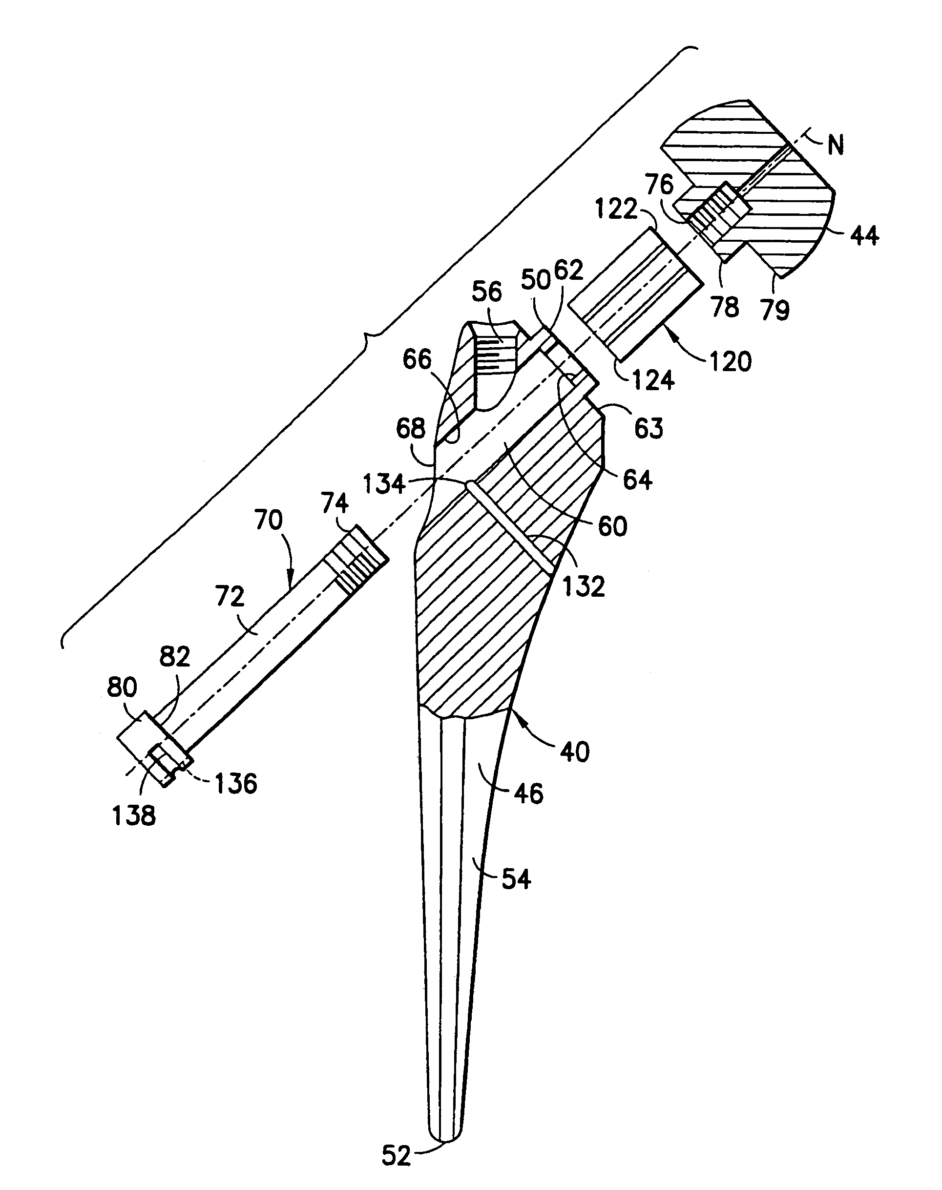
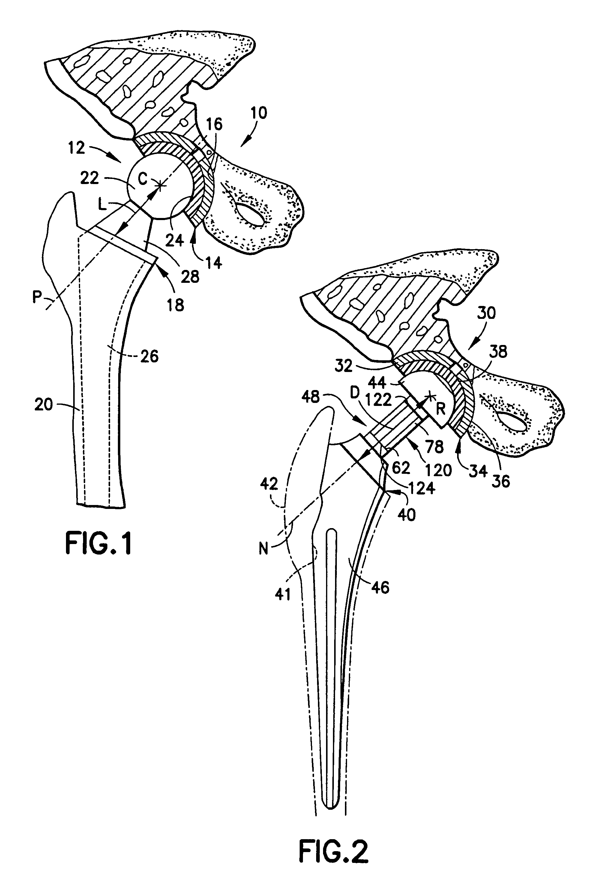
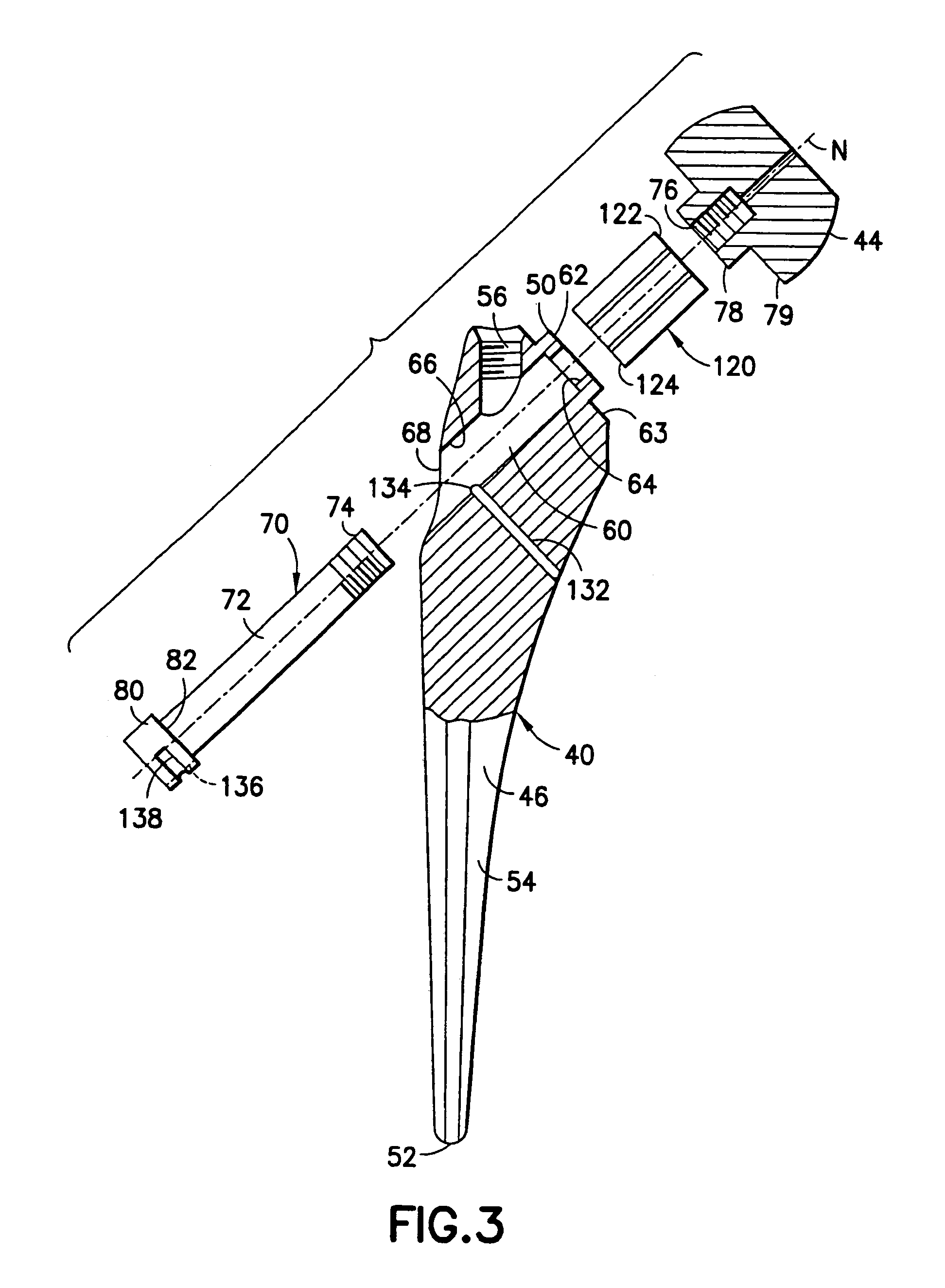
[0007]The present invention provides apparatus and method by which the appropriate head offset and neck length in a femoral component of a prosthetic hip joint is determined interoperatively with ease and with accuracy, for accomplishing optimal hip mechanics. As such, the present invention attains several objects and advantages, some of which are summarized as follows: Facilitates an interoperative determination of the appropriate head offset and neck length for a femoral component in a total hip arthroplasty; enables relatively quick and effective interoperative trialing for evaluation of hip mechanics at a prosthetic hip implant site; allows selective changes in the distance between the femoral stem of a femoral trial for a prosthetic hip joint and a femoral head of the femoral trial for interoperatively determining an appropriate head offset and neck length in the femoral component of the prosthetic hip joint itself, without the necessity for serial replacements of the entire trial and concomitant multiple dislocations of the hip joint; enables interoperative evaluation of hip mechanics at a hip implant site for consistent, precise results attained with ease and in less time; improves accuracy in the completion of a total hip arthroplasty; facilitates the conduct of minimally invasive total hip arthroplasty, where access to the hip joint is more limited; reduces pain and discomfort, as well as recovery time, in patients subjected to total hip arthroplasty.

Problems solved by technology

The procedure can be quite time-consuming and even physically challenging, especially with larger patients.
Moreover, the procedure is not suited to the conduct of more recently developed minimally invasive total hip arthroplasty where access to the hip joint is more limited.

Method used


Image

  • Hip arthroplasty trialing apparatus and method
  • Hip arthroplasty trialing apparatus and method
  • Hip arthroplasty trialing apparatus and method

Examples


Embodiment Construction

[0023]Referring now to the drawing, and especially to FIG. 1 thereof, an implant site 10 has been provided with a prosthetic hip joint 12 which is seen to include an acetabular component 14 implanted in acetabulum 16, and a femoral component 18 implanted in proximal femur 20. Femoral component 18 includes a femoral head 22, which is engaged with a bearing surface 24 of the acetabular component 14 for articulation of the prosthetic hip joint 12, a femoral stem 26, which is affixed within the proximal femur 20 to secure the femoral component 18 in place, and a femoral neck 28, which connects the femoral head 22 to the femoral stem 26 and which spaces the femoral head 22 from the femoral stem 26, all as now well-known in prosthetic hip joints.

[0024]As is conventional, prosthetic hip joint 12 relies upon soft tissue (not shown) at the implant site 10 to maintain femoral head 22 of femoral component 18 appropriately engaged with bearing surface 24 of acetabular component 14 for proper hi...


PUM


Abstract

A femoral head offset and neck length required in a femoral component to be engaged with an acetabular component are determined for establishing appropriate hip mechanics in a prosthetic hip joint. Alternate selected sleeves of different lengths are interposed between a trial femoral head component and a trial femoral stem component movable relative to one another to admit each selected sleeve, interoperatively, for serial trialing to determine an appropriate trial distance, the appropriate trial distance corresponding to the required femoral head offset and neck length in the prosthetic hip joint.

Description

BACKGROUND OF THE INVENTION[0001]1. Field of the Invention[0002]The present invention relates generally to hip arthroplasty and pertains, more specifically, to apparatus and method for conducting interoperative trialing to determine an appropriate head offset and neck length in the femoral component of a prosthetic hip joint.[0003]2. Description of the Related Prior Art[0004]Total hip arthroplasty requires the preparation of an implant site for the reception of a femoral component and an acetabular component of a prosthetic hip joint to be implanted at the implant site. Proper hip mechanics are achieved through the selection of an appropriate head offset and neck length in the femoral component of the prosthetic hip implant. That is, the distance between the stem of the femoral component and the femoral head of the component, provided by the length of the neck of the component, establishes the requisite head offset and neck length which, in turn, provides the desired range of motion...

Claims


Application Information

Patent Timeline
IPC IPC(8): A61F2/32
CPCA61F2/4684A61F2/34A61F2/36A61F2002/30433A61F2002/30492A61F2002/3055A61F2250/0007A61F2002/365A61F2002/3652A61F2002/4629A61F2220/0025A61F2220/0041A61F2002/30616
Inventor KUCZYNSKI, JOHN D.MAHONEY, ORMONDESRIVINI, GAUTAM N.
Owner HOWMEDICA OSTEONICS CORP
Learn More