Guide for acetabular component positioning

a technology for acetabular components and positioning guides, which is applied in the field of determining the positioning of acetabular components, can solve the problems of increasing the difficulty of visually aligning the two axes so as to be parallel, and achieves the effects of enhancing the accuracy of the procedure, and facilitating the visual alignment process

Active Publication Date: 2013-06-27
MURPHY STEPHEN B
View PDF3 Cites 15 Cited by
  • Summary
  • Abstract
  • Description
  • Claims
  • Application Information

AI Technical Summary

Benefits of technology

[0006]While the system described above provides a simpler, faster, and generally more accurate procedure for inserting an acetabular cup into the acetabulum with a desired orientation, I have developed a simple instrument for further enhancing the accuracy of the procedure.
[0007]In particular, the axis of the handle of the cup inserter, which the surgeon manipulates to align the inserter with the guide rod, is typically spaced at a distance of several inches from the axis of the guide rod, thereby increasing the difficulty of visually aligning the two axes so that they are parallel. To minimize alignment errors that may result from this, I provide a parallel guide that quickly and easily attaches to the ins...

Problems solved by technology

In particular, the axis of the handle of the cup inserter, which the surgeon manipulates to align the inserter with the guide rod, is typically spaced ...

Method used


Image

  • Guide for acetabular component positioning
  • Guide for acetabular component positioning
  • Guide for acetabular component positioning

Examples


Embodiment Construction

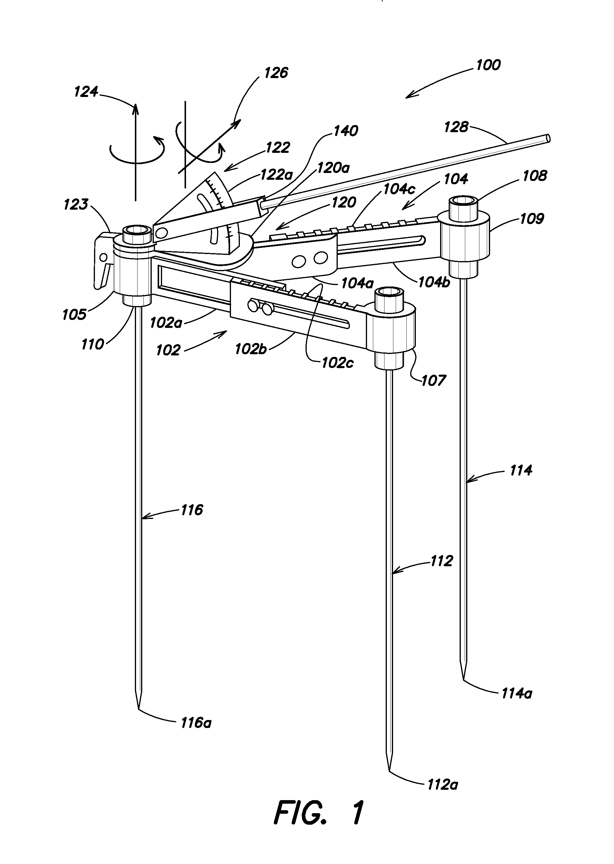
[0016]FIG. 4 of the '545 application is reproduced here as FIG. 1 for ease of reference; the same reference numbers have been retained. It shows a preferred form of the manual stereotactic instrument of the '545 application. The manner in which that instrument is used to define a reference plane for arthroplastic surgery is described in detail in that application. For present purposes, it suffices to understand that the guide rod 128 defines the direction in which an acetabular cup is to be inserted into a hip.

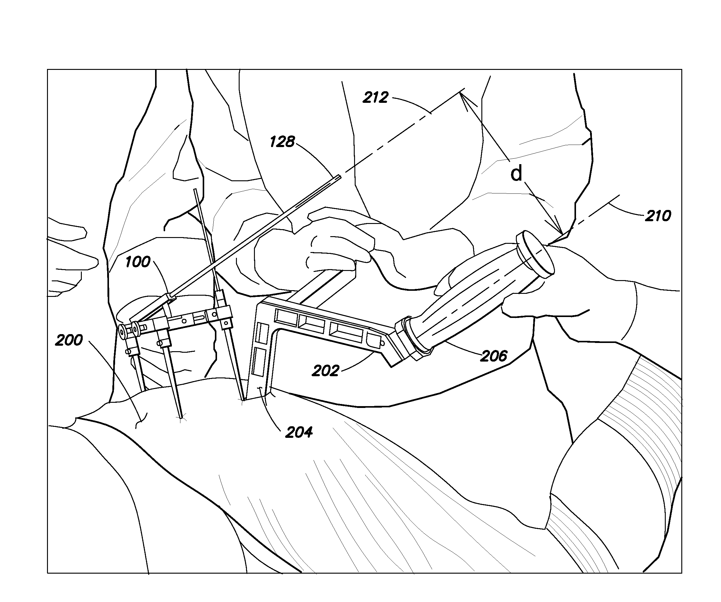
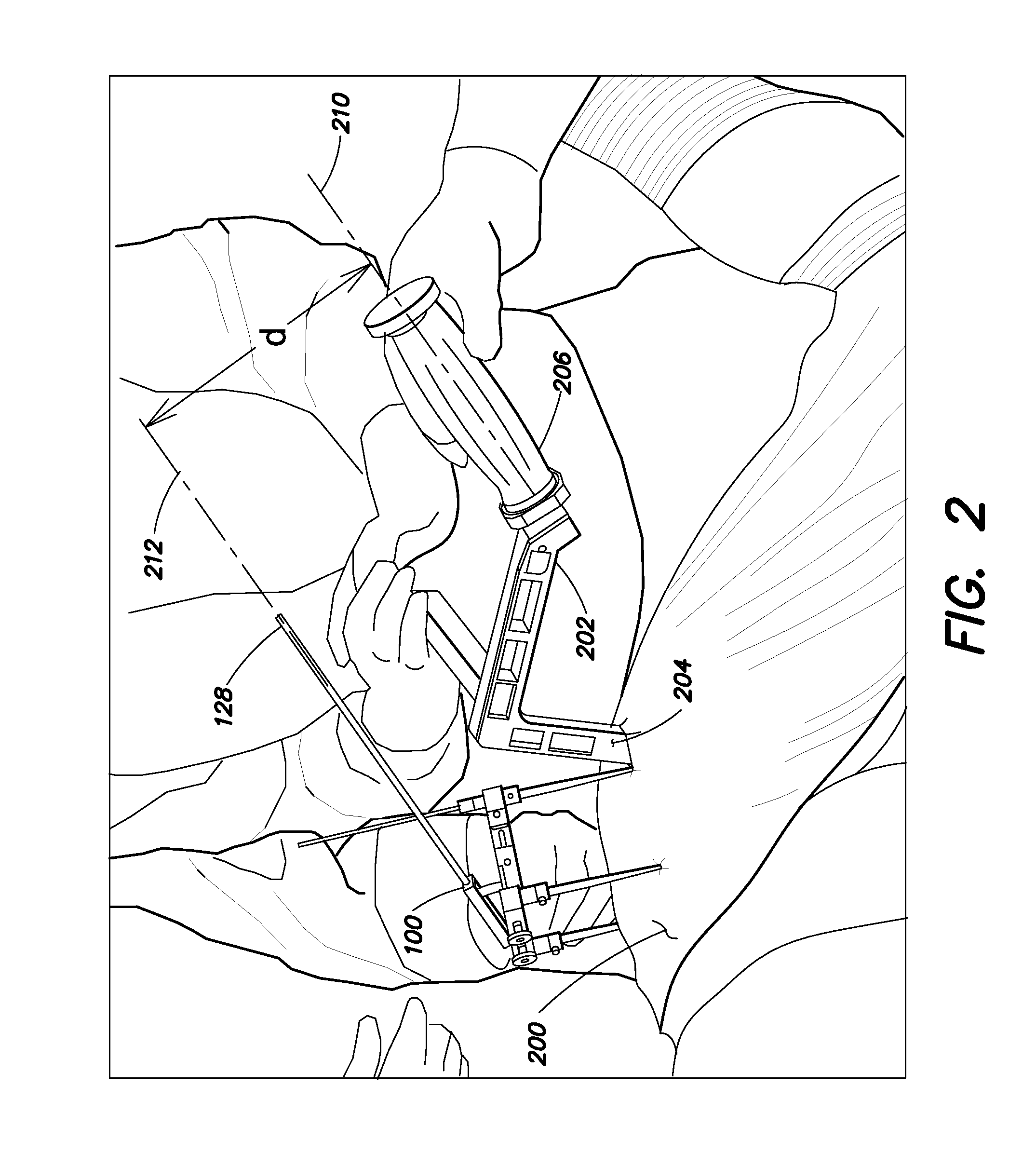
[0017]FIG. 2 shows the stereotactic instrument 100 positioned on a hip 200 during surgery. The guide 128 of the instrument, or an extension thereof, indicates the direction in which an acetabular cup is to be inserted. A cup inserter 202 of well known and commercially available type carries, at one end 204 thereof, an acetabular cup which is to be implanted in the patient; in FIG. 2, the cup is within the surgical incision and thus not visible. A handle 206 is formed at the ot...


PUM


Abstract

Apparatus for aligning a surgical instrument, such as an acetabular cup inserter, with a direction guide that defines an orientation in space for insertion of the cup. The apparatus comprises a parallel guide having a first arm for alignment with the direction guide and a second arm spaced from the first arm but maintained in parallel relationship with it. The cup inserter can be aligned with the first arm by aligning it with the second arm.

Description

CROSS-REFERENCE TO RELATED APPLICATIONS[0001]The present application claims the benefit of U.S. Provisional Patent Application Ser. No. 61 / 567,982, which was filed on Dec. 7, 2011, by Stephen B. Murphy for a ADAPTOR FOR ACETABULAR COMPONENT POSITIONING and is hereby incorporated by reference.[0002]This application is related to U.S. patent application Ser. No. 12 / 134,545, “Method And Apparatus For Determining Acetabular Component Positioning”, filed Jun. 6, 2008 by Stephen B. Murphy, claiming priority of U.S. Provisional Patent Application Ser. No. 60 / 984,425, filed Nov. 1, 2007, and published on Dec. 10, 2009 as U.S. Publication No. US-20090306679-A1, and the entire contents of which are expressly incorporated herein by reference.BACKGROUND INFORMATION[0003]The above application (“the '545 application”) describes a method and apparatus for determining acetabular component positioning, particularly for use in connection with hip arthroplasty. The method establishes a coordinate fram...

Claims


Application Information

Patent Timeline
IPC IPC(8): A61B17/88
CPCA61F2002/4687A61B19/201A61F2/4609A61B17/8897A61B90/11
Inventor MURPHY, STEPHEN B.
Owner MURPHY STEPHEN B
Why Eureka
Try Eureka