Acetabular component

Inactive Publication Date: 2010-10-07
ROBERTS PAUL +1
View PDF8 Cites 14 Cited by
  • Summary
  • Abstract
  • Description
  • Claims
  • Application Information

AI Technical Summary

Problems solved by technology

However, it has conventionally been considered that it would be highly undesirable for a hip resurfacing acetabular cup to be fixed in place using screws through holes in the bearing surface of the cup, due to the perceived risk to the lubrication and wear properties of the finished joint.
However, such techniques can be technically demanding and may result

Method used


Image

  • Acetabular component
  • Acetabular component
  • Acetabular component

Examples


Embodiment Construction

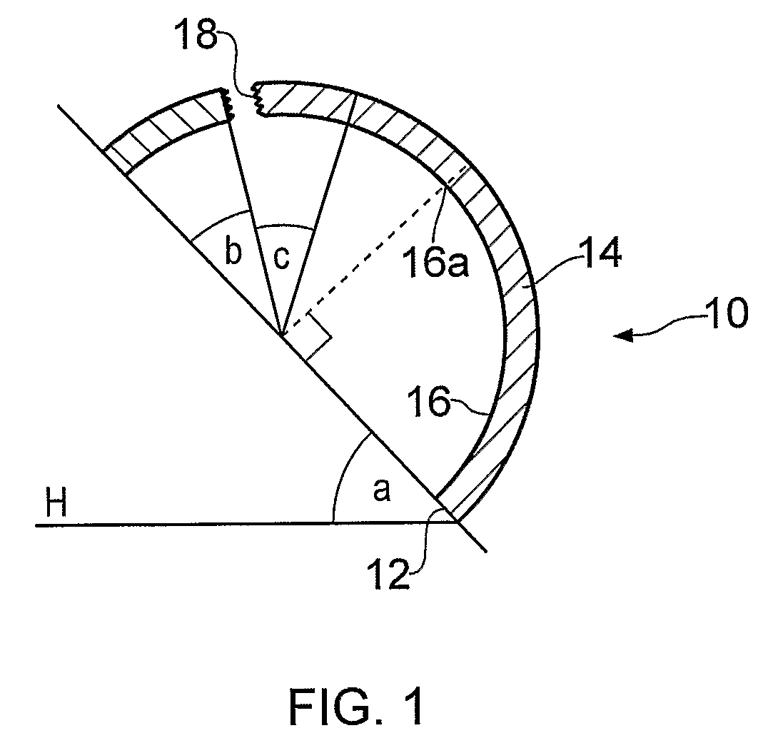
[0061]FIG. 1 shows a schematic cross-sectional view of an acetabular component 10 according to an embodiment of the invention, having a rim 12, a wall 14 and being formed to provide a substantially hemispherical concave bearing surface 16. The view of the component is taken along a plane coinciding with the diameter of the rim 12 and the point 16a of maximum depth of the inner bearing surface from the rim 12.

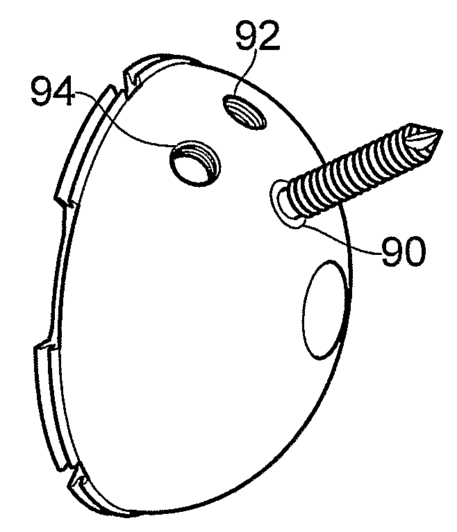
[0062]Screw hole 18 is provided through the thickness of wall 14.

[0063]The orientation of the component 10 to the horizontal line H is chosen to be such that angle a is about 45°. The location of screw hole 18 is chosen to be such that angle b is about 30°. It is intended that screw hole 18 (or a cluster of two or three screw holes) can be arranged in the area defined by angle c, which is also about 30°. The result of this is that the screw holes lie within about 15° of the vertical, substantially corresponding to the weight-bearing axis in use.

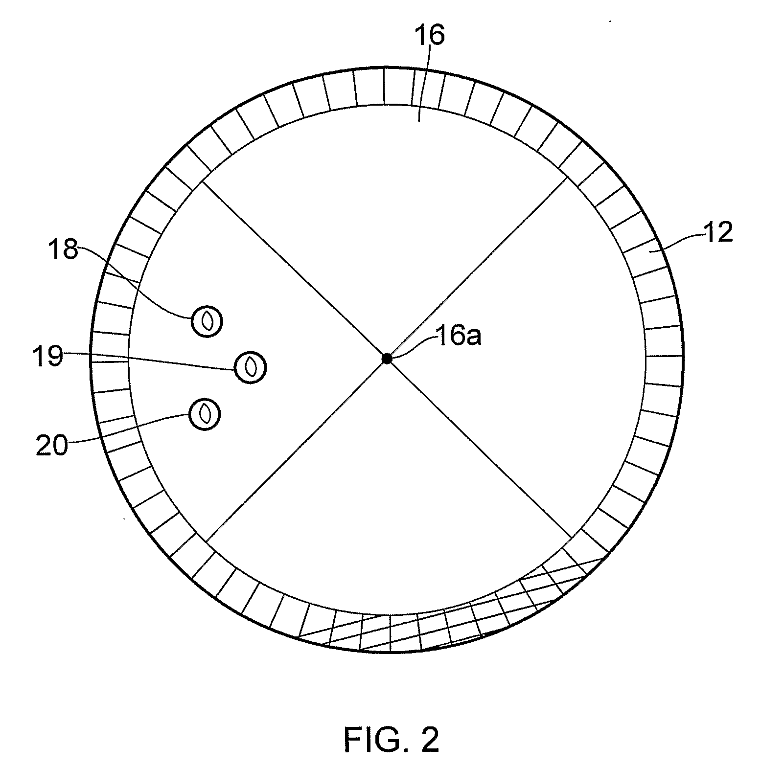
[0064]FIG. 2 shows a plan view of ...


PUM


Abstract

An acetabular component (10) for hip surgery has an outer convex surface for location in the acetabulum and an inner concave bearing surface (16) suitable for holding and bearing against a corresponding femoral head component, without need for an interposed liner. The outer convex surface and the inner concave surface define between them an integral wall (14) of the component. Screw holes (18) are provided though the wall, from the inner concave bearing surface to the outer convex surface for screw fixation of the component in the acetabulum.

Description

[0001]The present invention relates to acetabular components for use in hip surgery. The invention also relates to kits including such components and methods for implantation of such components.RELATED ART[0002]In conventional hip replacement surgery, the replacement joint comprises a femoral part (which is intended to be inserted or implanted into the femur and which carries a ball-shaped articulation element) and an acetabular cup (which is intended to be inserted into the acetabulum). The acetabular cup is designed to hold a complementary cup-shaped liner (typically formed of plastics material), in which the ball-shaped element is to articulate.[0003]One prior art document showing such an arrangement is WO 95 / 17140, in which the acetabular cup has a design including barb-shaped beads provided at the outer periphery to allow the cup to be pushed into a cavity formed in the acetabulum, these beads counteracting the removal of the cup from the cavity. As will be well understood, acc...

Claims


Application Information

Patent Timeline
IPC IPC(8): A61F2/32
CPCA61B17/86A61F2/30744A61F2/34A61F2310/00029A61F2002/3404A61F2002/3446A61F2002/3401A61F2002/3403
Inventor ROBERTS, PAULGRIGORIS, PETER
Owner ROBERTS PAUL
Why Eureka
Try Eureka