Annuloplasty instrument

a technology of annuloplasty and valve body, which is applied in the field of heart valve repair and replacement techniques and annuloplasty devices, can solve the problem of the small risk of having to reposition the annuloplasty implant, and achieve the effect of convenient insertion of the annuloplasty implant and more reliable and convenient valve repair

Inactive Publication Date: 2006-07-18
MEDTENTIA INT LTD OY
View PDF36 Cites 326 Cited by
  • Summary
  • Abstract
  • Description
  • Claims
  • Application Information

AI Technical Summary

Benefits of technology

[0007]It is an object of the invention to provide a more reliable and more easily accomplished valve repair. It is a specific object of the invention to facilitate insertion of an annuloplasty implant.
[0010]The implantation instrument is applied to the heart valve in a much easier manner than conventionally utilized annuloplasty rings. By means of the implantation instrument it is possible to fixate the valve annulus and primarily reshape it. This primary reshaping of the valve annulus facilitates attachment of the annuloplasty implant to the valve annulus. There is merely a need for a slight further reshaping of the valve annulus by the attachment of the annuloplasty implant in order to achieve the desired shape of the valve annulus. Since the attachment of the annuloplasty implant need not dramatically change the shape of the valve annulus, the possibility of correctly positioning the annuloplasty implant is greatly increased. This implies that there is a very slim risk that the annuloplasty implant will need to be repositioned. Further, by means of the device the desired reshaping of the valve annulus may in most cases be achieved.
[0013]At least the opposed surfaces of the first and second support rings may be roughened, such as by the use of fabric, coatings, knurling or the like to facilitate better engagement and retention of the support rings on the valve tissue. The opposed surfaces may be roughened in a pattern extending along the longitudinal direction of the rings. This implies that the roughened surface will serve to prevent slippage of tissue through the ring while presenting a low friction for the ring to be turned into position abutting the valve. The implantation instrument may have an inherent shape where the first and second rings contact or nearly contact each other. Thus, the implantation instrument will present a spring force pushing the first and second rings towards each other. The spring force will make the first and second rings fixating valve tissue between them.
[0017]According to a second aspect of the invention, a kit is provided for repairing a heart valve comprised of valve tissue including an annulus and a plurality of leaflets for allowing and preventing blood flow. The kit comprises an implantation instrument, which comprises a first support ring, and a second support ring connected to the first support ring to form a coiled configuration. The first support ring is configured to abut one side of the valve and the second support ring is configured to abut an opposite side of the valve to thereby trap a portion of the valve tissue therebetween. The kit further comprises an annuloplasty implant adapted to be attached to the heart valve annulus in order to reshape the annulus and allow the leaflets to open and close properly.
[0020]The step of inserting the instrument may comprise temporarily reshaping the annulus to facilitate attachment of the annuloplasty implant to the annulus. Thus, the implantation instrument will guide the positioning of the annuloplasty implant.
[0021]The step of inserting may further comprise inserting a first end of the first support ring through a portion of the valve tissue, rotating the implantation instrument to position the first support ring on a first side of the valve, and positioning the second support ring on an opposite second side of the valve. The first and second support ring are thus easily applied on opposite sides of the valve.

Problems solved by technology

This implies that there is a very slim risk that the annuloplasty implant will need to be repositioned.

Method used


Image

  • Annuloplasty instrument
  • Annuloplasty instrument
  • Annuloplasty instrument

Examples


Embodiment Construction

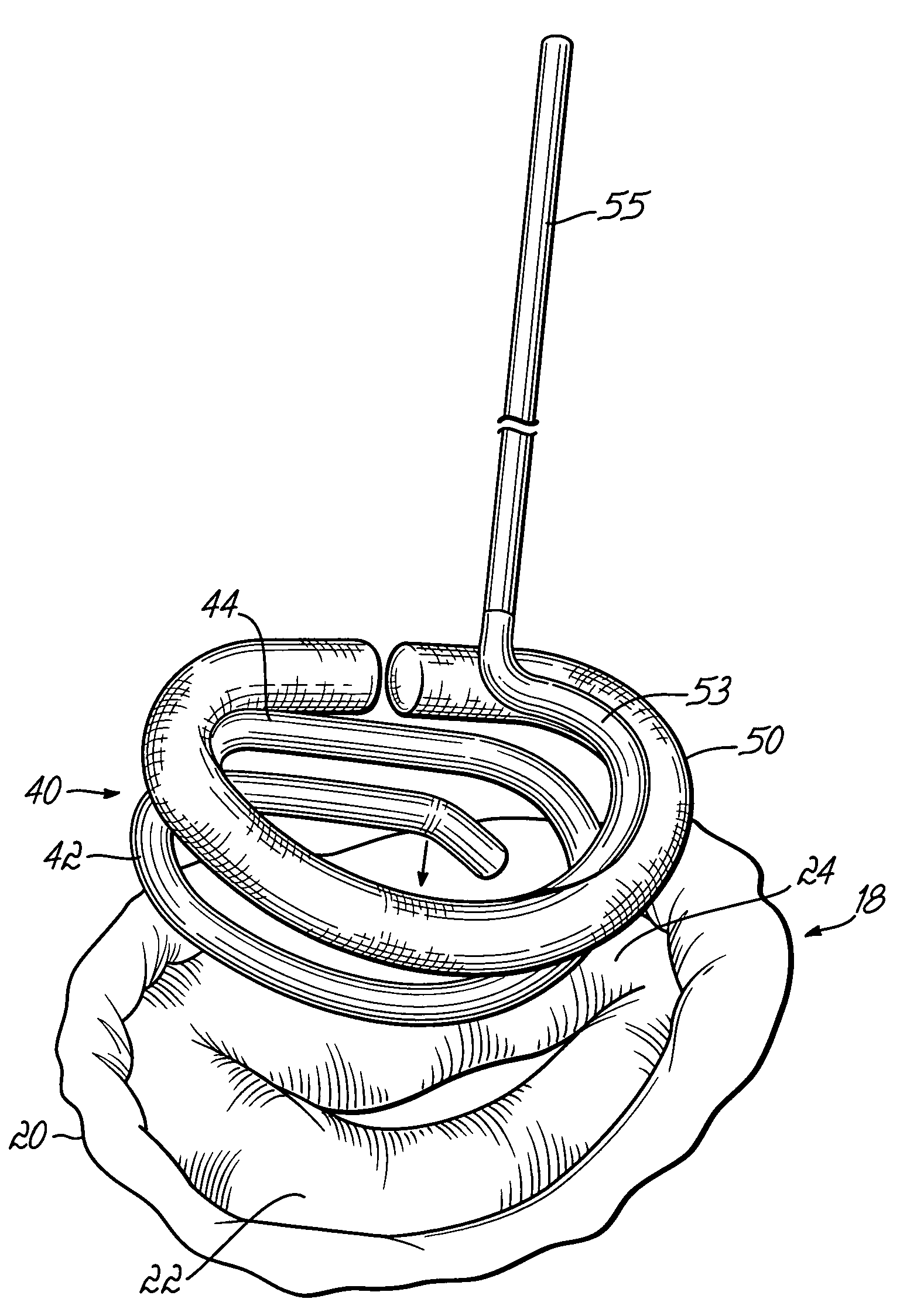
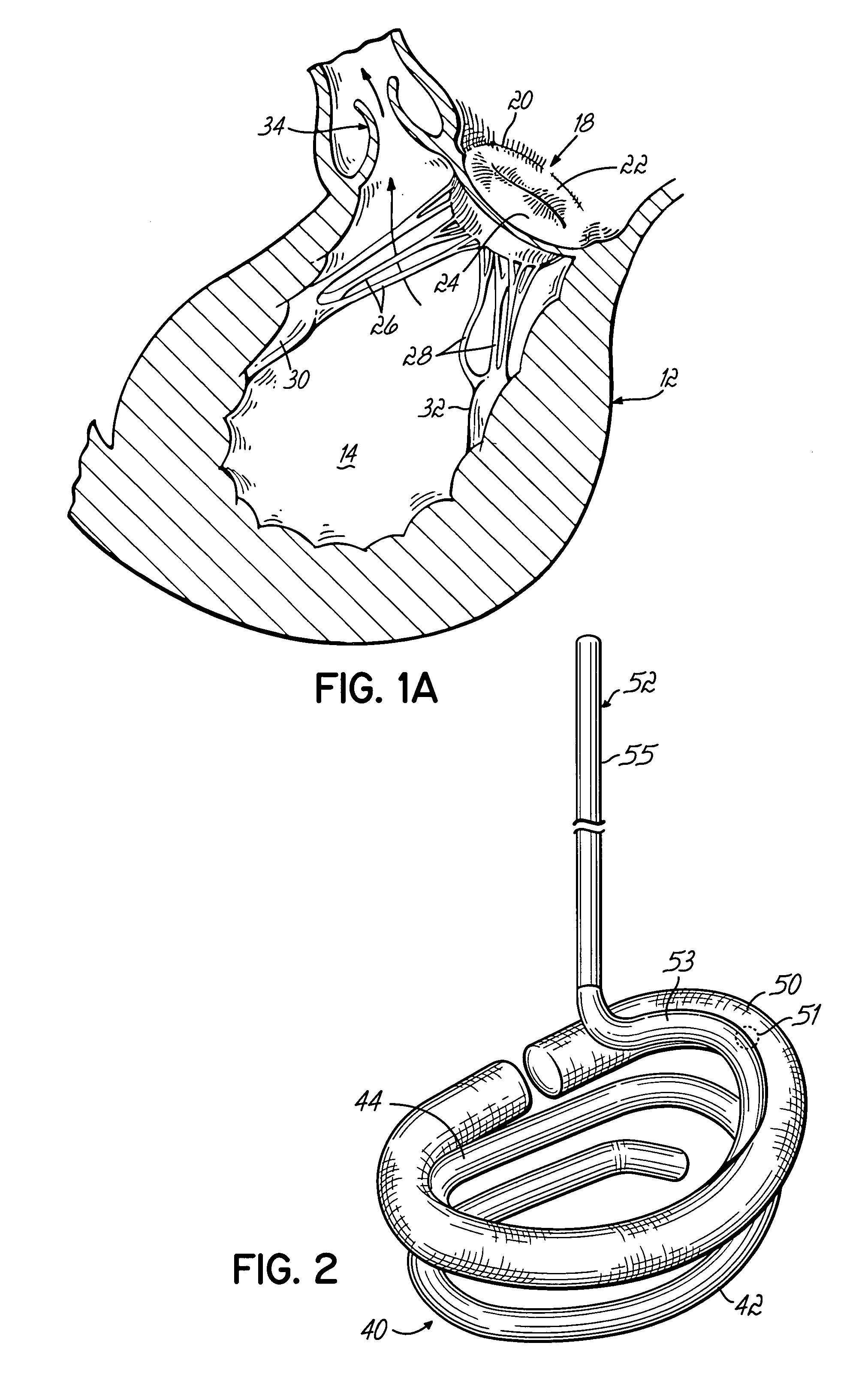
[0036]FIG. 1 illustrates a patient 10 having a heart 12 shown in cross section including a left ventricle 14 and a right ventricle 16. The concepts of the present invention are suitable to be applied, for example, to a mitral valve 18 which supplies blood into left ventricle 14. Mitral valve 18, as better shown in FIG. 1A, includes an annulus 20 and a pair of leaflets 22, 24 which selectively allow and prevent blood flow into left ventricle 14. It will be appreciated that the term annulus tissue is used extensively throughout this disclosure in reference to the drawings, however, the inventive principles are equally applicable when referring to other valve tissue such as leaflet tissue or other attached vessel tissue. Leaflets 22, 24 are supported for coaptation by chordae tendinae or chords 26, 28 extending upwardly from respective papillary muscles 30, 32. Blood enters left ventricle 14 through mitral valve 18 and is expelled during subsequent contraction of heart 12 through aorti...


PUM


Abstract

A device for repairing a heart valve comprises an implantation instrument. The implantation instrument comprises a first support ring, and a second support ring connected to said first support ring to form a coiled configuration. The first support ring is configured to abut one side of the valve and the second support ring is configured to abut an opposite side of the valve to thereby trap a portion of the valve tissue therebetween. The device further comprises an annuloplasty implant adapted to be attached to the heart valve annulus in order to reshape the annulus and allow the leaflets to open and close properly. The annuloplasty implant is connected to the implantation instrument for insertion to the annulus.

Description

[0001]This application is a continuation-in-part of application Ser. No. 10 / 787,581, filed on Feb. 26, 2004 now U.S. Pat. No. 6,964,684 (pending) which is a divisional of application Ser. No. 10 / 145,416 filed on May 14, 2002 (now U.S. Pat. No. 6,730,121) which is a divisional of application Ser. No. 09 / 610,784 filed Jul. 6, 2000 (now U.S. Pat. No. 6,419,696), the disclosures of which are fully incorporated herein by reference.FIELD OF THE INVENTION[0002]The present invention generally relates to heart valve repair and replacement techniques and annuloplasty devices. More specifically, the invention relates to the repair of heart valves having various malformations and dysfunctions.BACKGROUND OF THE INVENTION[0003]Diseased mitral and tricuspid valves frequently need replacement or repair. The mitral and tricuspid valve leaflets or supporting chordae may degenerate and weaken or the annulus may dilate leading to valve leak (insufficiency). The leaflets and chords may become calcified ...

Claims


Application Information

Patent Timeline
Patent Type & Authority Patents(United States)
IPC IPC(8): A61F2/24A61F2/00
CPCA61F2/2445A61F2/2466A61F2/2448A61F2/2427A61F2210/0033A61F2230/0091
Inventor SPENCE, PAUL A.
Owner MEDTENTIA INT LTD OY
Why Eureka
Try Eureka