

Mechanical locking system for building panels
a technology of mechanical locking and building panels, applied in the direction of mechanical apparatus, dismountable cabinets, furniture parts, etc., can solve the problems of complex and time-consuming assembly, many problems connected with the assembly of furniture components, and often insufficient connection, etc., to achieve the effect of simple manner
- Summary
- Abstract
- Description
- Claims
- Application Information
AI Technical Summary
Benefits of technology
Problems solved by technology
Method used
Image

Examples
embodiment 1
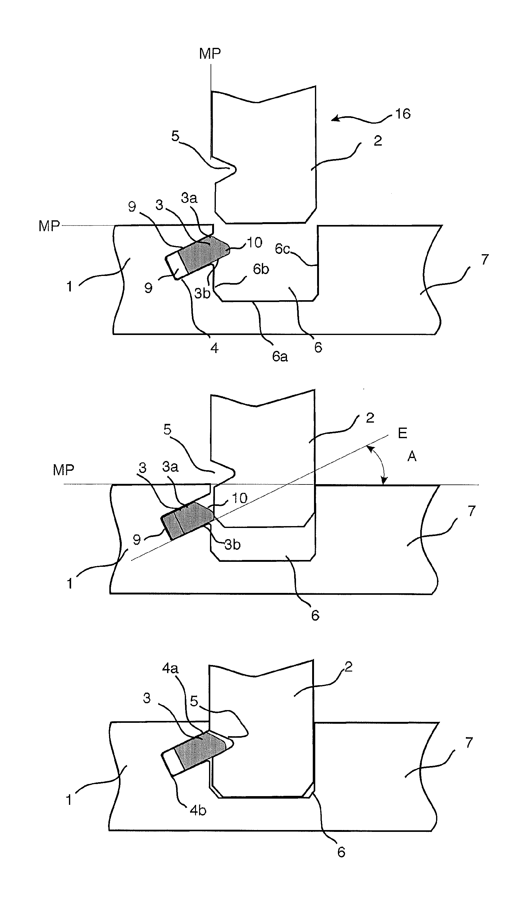
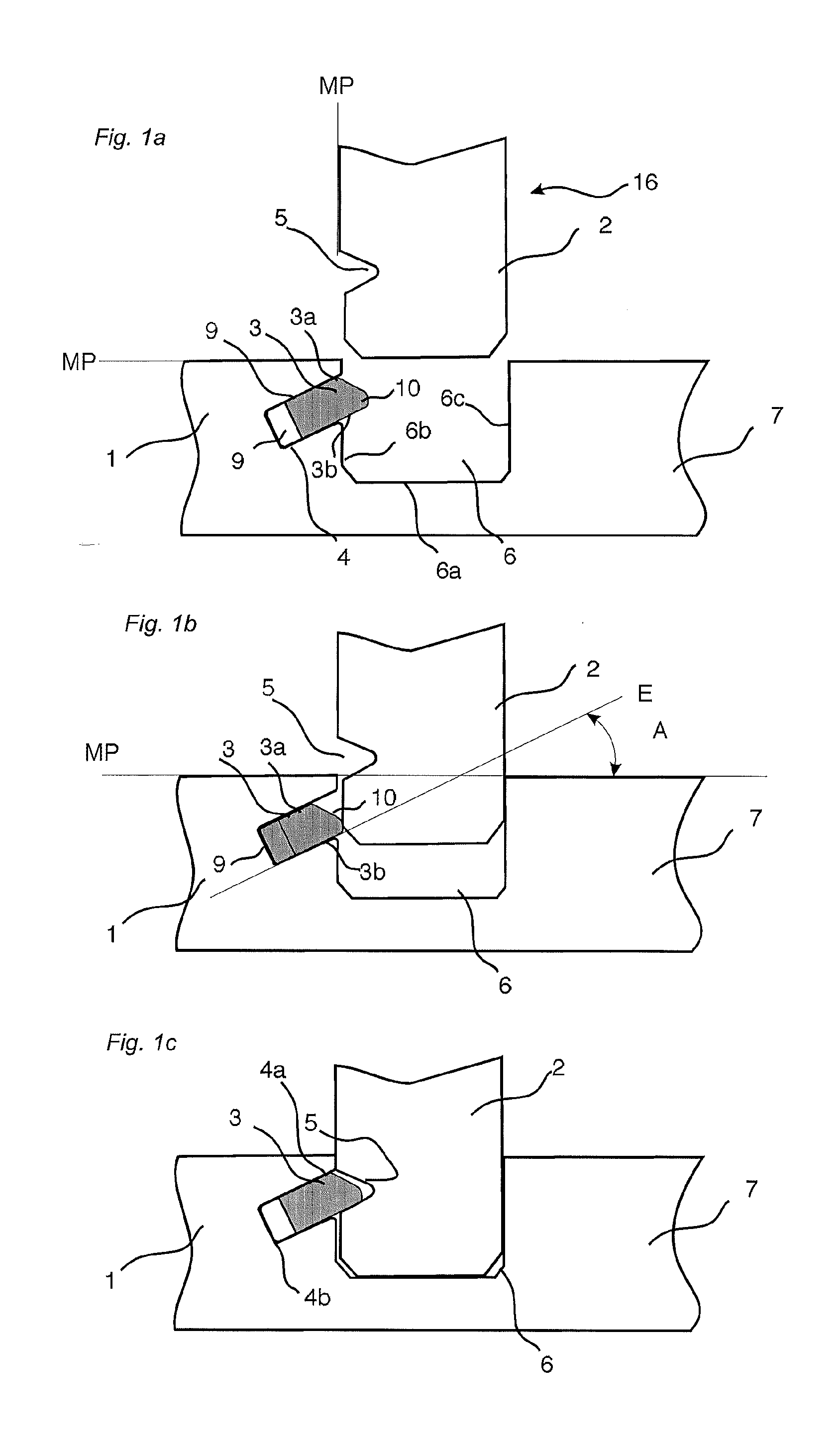
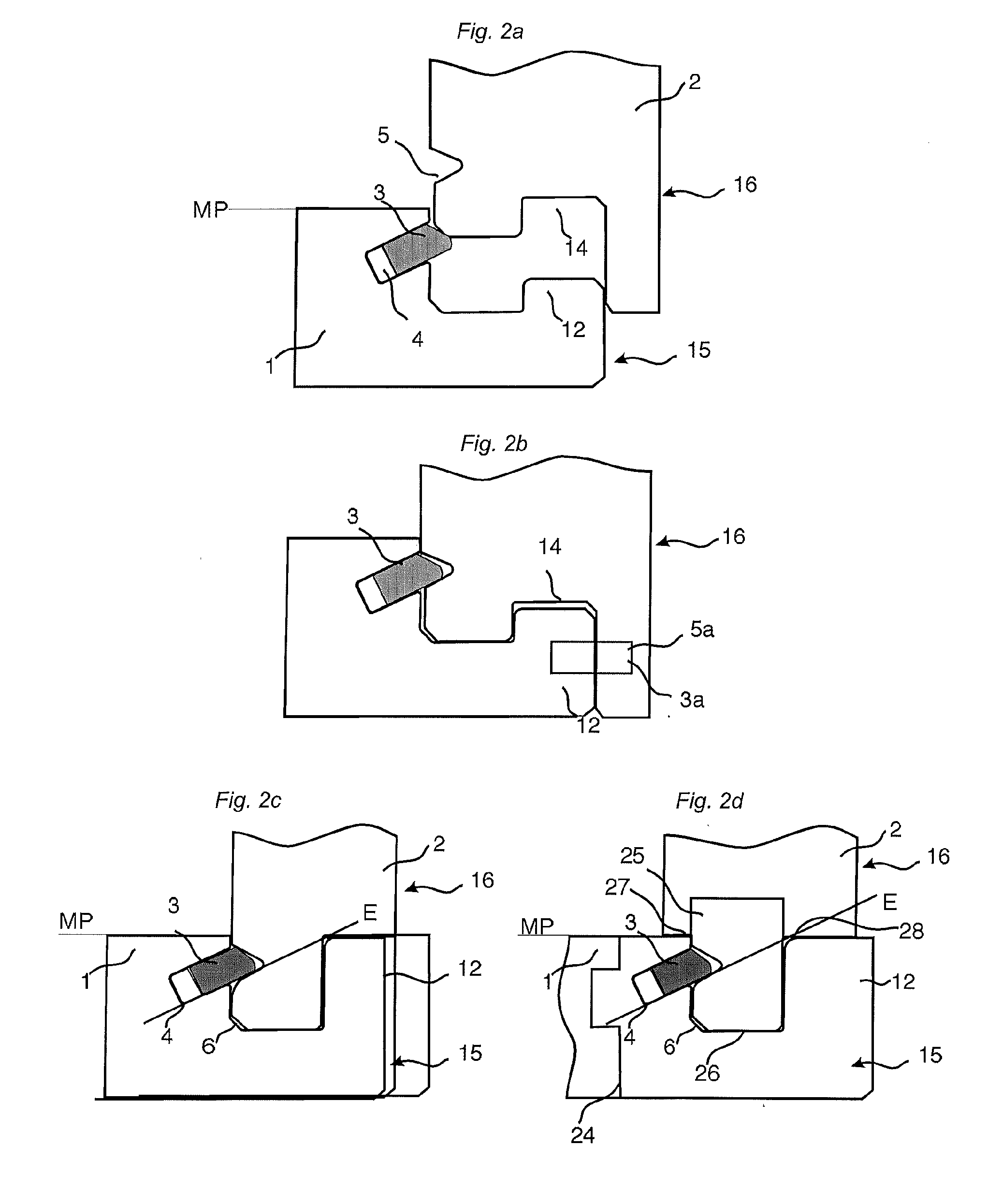
[0067]2. The set of panels as recited in embodiment 1, wherein the flexible tongue has two opposite displacement surfaces (3a, 3b) located between the inner and the outer parts, each of the two opposite displacement surfaces of the flexible tongue (3) are displaceable against an upper and a lower wall respectively of the insertion groove during locking, inwardly towards the bottom of the insertion groove (4) and outwardly into the tongue groove (5).
[0068]3. The set of panels as recited in embodiment 1 or 2, wherein the said insertion groove (4) is inclined upwards with the opening closer to the main plane (MP) of the panel than the inner part insertion groove (4).
[0069]4. The set of panels as recited in any of the preceding embodiments, wherein the insertion groove (4) is inclined such that an extension E of its lower part is located at or above the upper part of the opening of the groove (6).
[0070]5. The set of panels as recited in any of the preceding embodiments, wherein the seco...
embodiment 15
[0081]16. The set of panels as recited in embodiment 15, wherein the separate material is covered with a foil.
PUM
| Property | Measurement | Unit |
|---|---|---|
| angle | aaaaa | aaaaa |
| angle | aaaaa | aaaaa |
| angle | aaaaa | aaaaa |
Abstract
Description
Claims
Application Information