Medical manipulator for use with an imaging device

a technology of manipulator and imaging device, which is applied in the field of manipulators, can solve the problems of time-consuming and imprecise, difficulty or unsafe for human operators to adjust the position of biopsy needles,

Inactive Publication Date: 2003-12-16
MICRODEXTERITY SYST
View PDF67 Cites 349 Cited by
  • Summary
  • Abstract
  • Description
  • Claims
  • Application Information

AI Technical Summary

Benefits of technology

A manipulator according to the present invention is particularly suitable for manipulating needles, such as biopsy needles. According to one form of the present invention, a needle for use with a manipulator can be assembled from a plurality of needle sections. The needle may be assembled while imaging of a patient is taking place immediately before the needle is inserted into the patient, and the needle may be disassembled into the individual needle sections as it is being withdrawn from the patient. The ability to assembly a needle from a plurality of needle sections makes the insertion of an elongated needle into a patient much easier and enables the manipulator to be introduced into crowded spaces which could not be accessed with a one-piece needle of the same length.
A manipulator according to the present invention enables a medical tool to be manipulated inside tight spaces in which it would be difficult or impossible for a human operator to position a tool or in environments which would be unsafe for a human operator. In particular, the manipulator can manipulate a medical tool with respect to a patient inside imaging equipment, which tend to have very small clearance surrounding a patient's body during imaging. Therefore, the manipulator enables the position of a medical tool with respect to a patient to be adjusted while imaging is taking place and makes it unnecessary to remove the patient from the imaging equipment each time the position of the tool needs to be adjusted. For this reason, the medical tool can be positioned quickly and accurately, enabling a medical procedure to be performed with the tool efficiently and economically with less stress on the patient. The ability of the tool to be rapidly positioned is particularly advantageous when the tool is being positioned in or near the patient's chest and the patient is holding his breath.
The manipulator can also reduce the fatigue experienced by a human operator, since it is unnecessary for the operator to physically support the medical tool during manipulation. The operator can let go of the manipulator while performing other tasks without the medical tool undergoing movement. Thus, the positional stability of the medical tool can be improved compared to when it is supported by hand. The ability of the operator to perform other tasks while the medical tool is supported by the manipulator can increase work efficiency and enable him to complete imaging more rapidly.
Furthermore, the manipulator can enhance the dexterity of the operator, i.e., it can enable him to manipulate a medical tool with greater dexterity than he could if directly handling the tool in his hands. For example, the manipulator can scale up or down the magnitudes of the operator's hand motions or the forces he applies, it can eliminate the effects of tremor in his hands, and it can help him to guide the tool along a path avoiding delicate regions of the patient's body.

Problems solved by technology

It is frequently difficult or unsafe for a human operator to adjust the position of the biopsy needle while an image of the patient's body is being taken due to the small amount of space between the interior of the imaging equipment and the patient's body, due to the undesirability of the operator being exposed to radiation from the imaging equipment, or due to the operator interfering with imaging if standing close enough to the patient to manipulate the biopsy needle.
Since the operator cannot view the position of the biopsy needle within the patient's body as he adjusts the position, the process of positioning the biopsy needle is essentially one of trial and error and so can be time-consuming and imprecise.
The same problems occur with procedures other than biopsies, such as during the insertion of catheters.

Method used


Image

  • Medical manipulator for use with an imaging device
  • Medical manipulator for use with an imaging device
  • Medical manipulator for use with an imaging device

Examples


Embodiment Construction

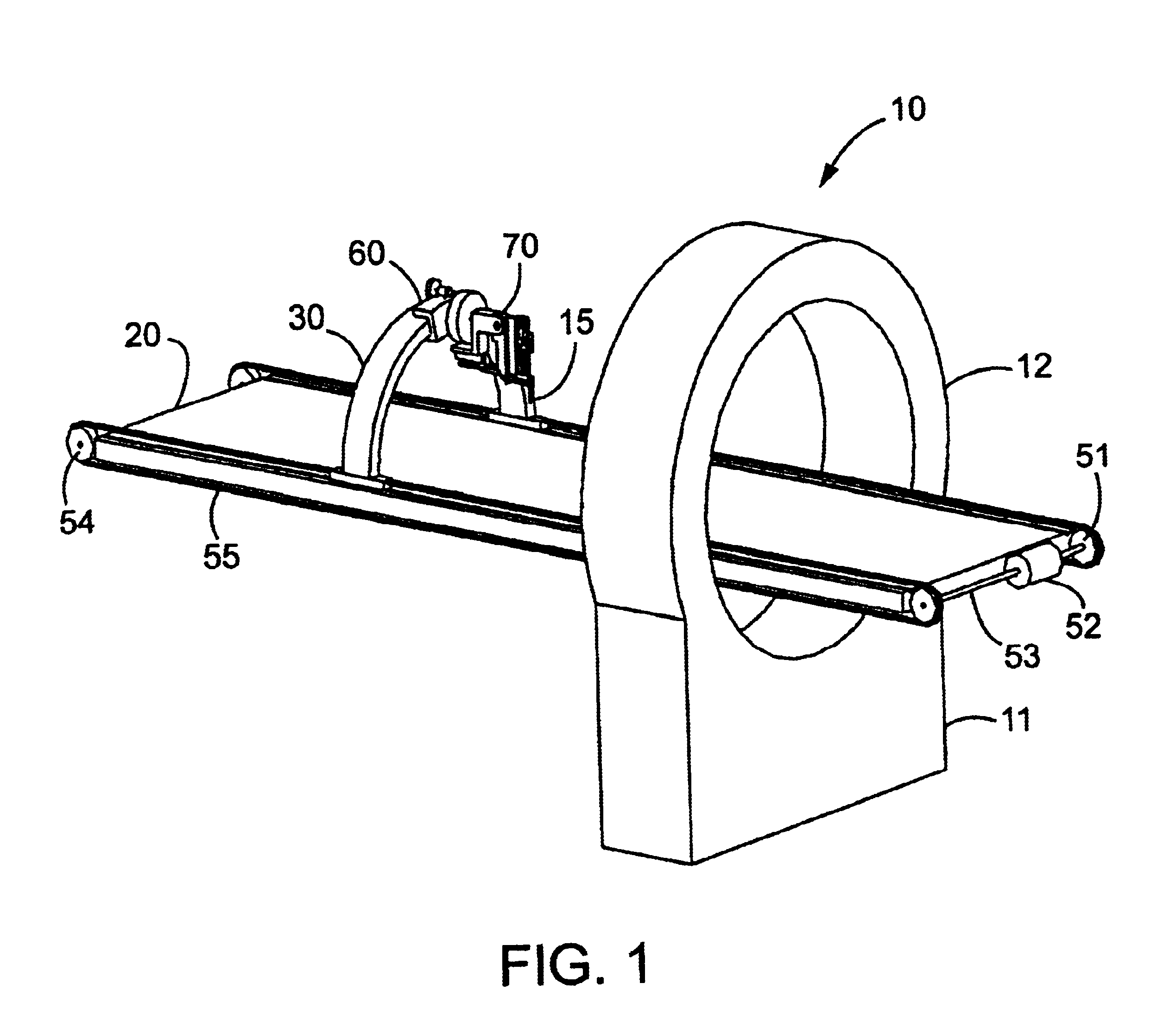
FIG. 1 schematically illustrates an embodiment of a manipulator according to the present invention for manipulating a medical tool. The manipulator is shown installed on a computer tomography (CT) machine 10, but as explained above, a manipulator according to the present invention can be used with other types of imaging devices and can also be employed separately from an imaging device.

The computer tomography machine 10, which may be of any desired type, typically includes a base 11, a donut-shaped portion, usually referred to as a gantry 12, mounted on the base 11 and containing imaging equipment, and a table 20 for supporting a patient during imaging. The table 20, which may be supported by the base 11 or other structure, is usually movable in its lengthwise direction through the gantry 12 to position the patient with respect to the imaging equipment within the gantry 12.

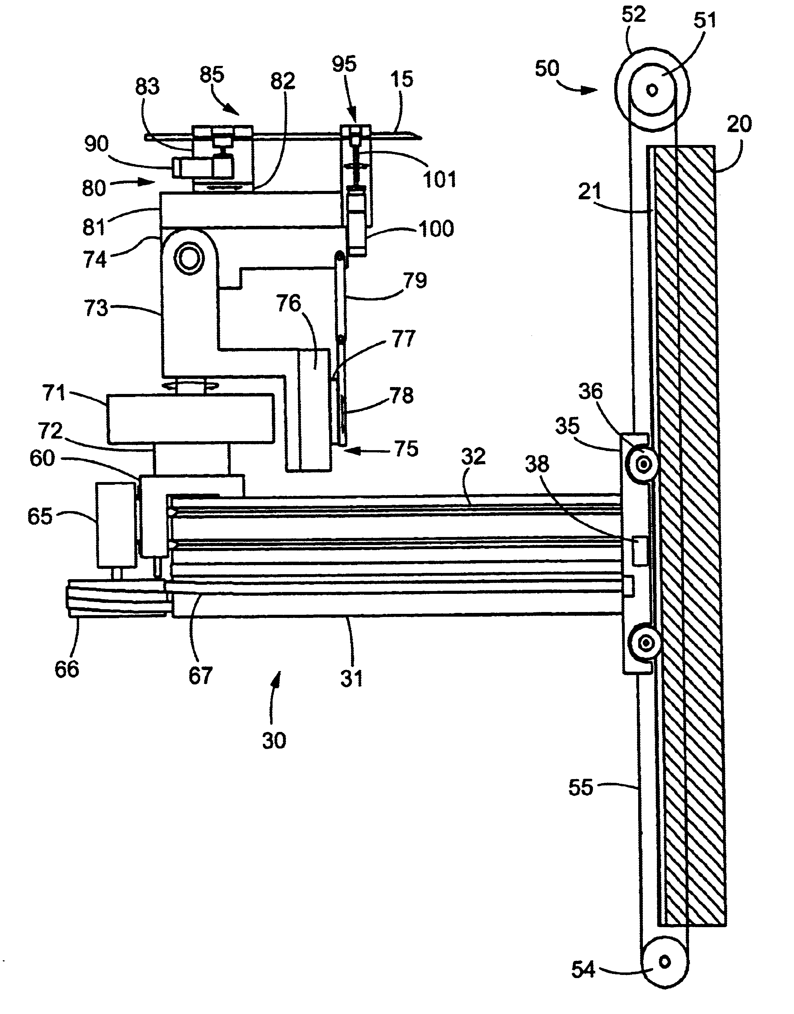
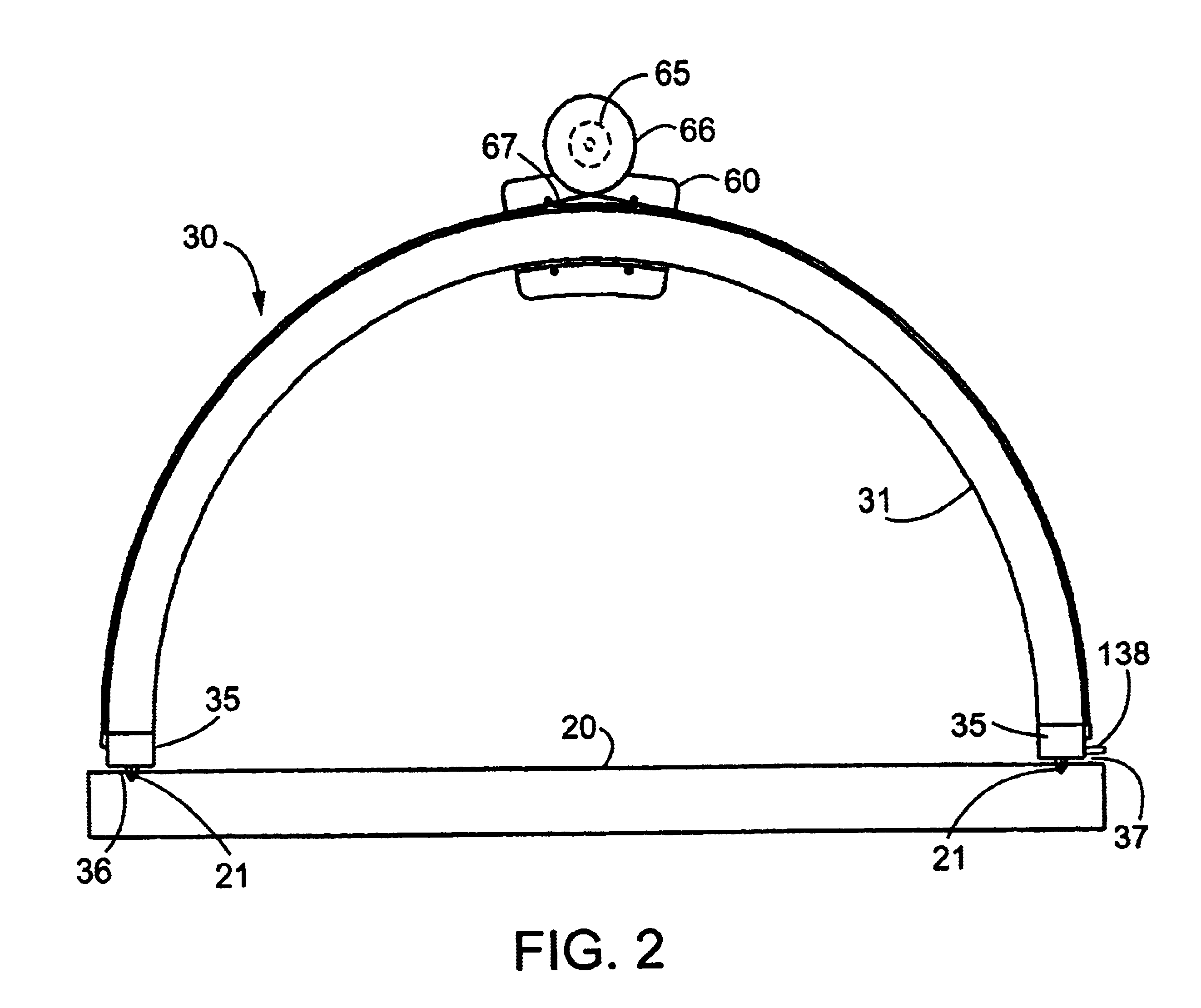
The manipulator includes a guide 30, a carriage 60 mounted on the guide 30 for movement above a patient lying o...


PUM


Abstract

A manipulator for use in medical procedures can manipulate a medical tool with one or more degrees of freedom with respect to a patient. The manipulator is particularly useful for positioning a medical tool with respect to a patient disposed inside an imaging device such as a computer tomography machine.

Description

1. Field of the InventionThis invention relates to a manipulator, and particularly to a manipulator suitable for use in conjunction with medical imaging devices.2. Description of the Related ArtMedical biopsies and other medical procedures are frequently performed in conjunction with imaging equipment, such as CT (computer tomography) equipment, conventional x-ray equipment, magnetic resonance imaging equipment, or other imaging equipment. In a biopsy performed with such imaging equipment, a biopsy needle is inserted into a patient's body while the patient is outside the imaging equipment, the patient is placed inside the imaging equipment, and then an image is taken of the patient's body with the imaging equipment to determine the location of the biopsy needle with respect to the region where the biopsy is to be performed. It is frequently difficult or unsafe for a human operator to adjust the position of the biopsy needle while an image of the patient's body is being taken due to ...

Claims


Application Information

Patent Timeline
Patent Type & Authority Patents(United States)
IPC IPC(8): A61B19/00A61B17/00A61B10/00A61B10/02
CPCA61B19/201A61B19/22A61B19/52A61B10/02A61B2019/464A61B2019/2276A61B2019/265A61B2019/462A61B2017/00398A61B34/70A61B90/11A61B90/36A61B2034/742A61B2090/062A61B2090/064A61B2090/506
Inventor CHARLES, STEVE T.STUART, J. MICHAEL
Owner MICRODEXTERITY SYST
Why Eureka
Try Eureka