Reverse total hip replacement

a total hip and femoral technology, applied in the field of hip replacement arthroplasty, can solve the problems of increasing the risk of femoral neck fracture, affecting the function of the hip joint, and most likely failing to implant this device into the hip joint, so as to achieve the effect of reversing the biomechanics and less for

Active Publication Date: 2017-02-09
LOFFREDO NICHOLAS JOHN
View PDF5 Cites 12 Cited by
  • Summary
  • Abstract
  • Description
  • Claims
  • Application Information

AI Technical Summary

Benefits of technology

[0013]This method effectively reverses the native articulating biomechanics of the ball and socket hip joint. The reverse total hip prosthesis medializes the center of rotation of the hip joint. Therefore, this method provides an advantage to the standard total hip replacement because the reverse prosthesis requires less force for the abductor muscles to move the joint. This can be an important advantage with revision surgery when surrounding soft tissue is scarred or damaged from previous surgery or infection.
[0016]The disclosed method also has an advantage to the standard hip replacement because it does not require reaming of the medial wall of the acetabulum. This is most beneficial because this wall of the acetabulum can be thin and lead to migration of the cup into the pelvis. The medial wall of the acetabulum can be exceptionally thin or nonexistent in revision total hip replacements where previous bone reaming has already occurred. The reverse design places the ball component on the acetabular side. Therefore, the acetabular reamer need not be hemi spherically shaped. The apex of the spherical portion of the reamer need not exist. Thus, the reamer can substantially take on the shape of a spherical segment, defined as a portion of a sphere that has been cut by parallel planes. This enables more bone to be spared from resection during the procedure.
[0018]Thus in one aspect the disclosure relates to a reverse hip replacement prosthesis device comprising a femoral component and an acetabular component for implantation into a human femur and a human acetabulum wherein the femoral component further comprises a cup portion and a stem portion for implantation to the human femur and wherein the cup portion attachably accepts a saucer-shaped spacer. The acetabular component further comprises an acetabular ball which fixes to an acetabular base for implantation into the human acetabulum, the acetabular base having substantially the shape of a spherical segment at its interface with the acetabulum, thereby preserving the native thickness of the medial acetabulum. The femoral component replaces a portion of a human femur and the acetabular component replaces the acetabular human socket, and wherein the cup portion of the femoral component articulates with the acetabular ball, thereby reversing the human articulating biomechanics of ball and socket hip joints.
[0023]ii) orienting the acetabular base such that the acetabular bridge is in a substantially anterior to posterior orientation enabling optimal trajectory of acetabular fasteners for attaching the acetabular base to the acetabulum;

Problems solved by technology

Many orthopedic surgeons began using this new innovative prosthesis until clinical studies showed an increase risk of femoral neck fracture in women (Powell, Belzile, Antoniou, et al., 2014).
This is not a large number but for those patients unfortunate enough to experience a dislocation the repercussions can be devastating.
Implanting this device into the hip joint would most certainly fail for a multitude of reasons.
This glenoid component could not be implanted into the acetabulum because of the limited bone stock in the medial wall of the acetabulum.
Therefore, this design would not be suitable for the hip because the femoral head has an anatomic neck which aligns the articular surface at 125 degrees from the shaft.
This failure is a result of loosening of the acetabular component which is ultimately pulled away from the pelvis secondary to the interlocking design (Yang, C., Goodman, S B.
This design did not include an interlocking system, though, this design has many practical limitations for clinical use.
Furthermore, this design is especially prone to acetabular loosening because element 118 of the FIG. 12 creates a lever arm with weight bearing on the acetabular component base.

Method used


Image

  • Reverse total hip replacement
  • Reverse total hip replacement
  • Reverse total hip replacement

Examples


Embodiment Construction

[0047]The present description is directed in particular to elements forming part of, or cooperating more directly with, apparatus in accordance with the invention. It is to be understood that elements not specifically shown or described may take various forms well known to those skilled in the art.

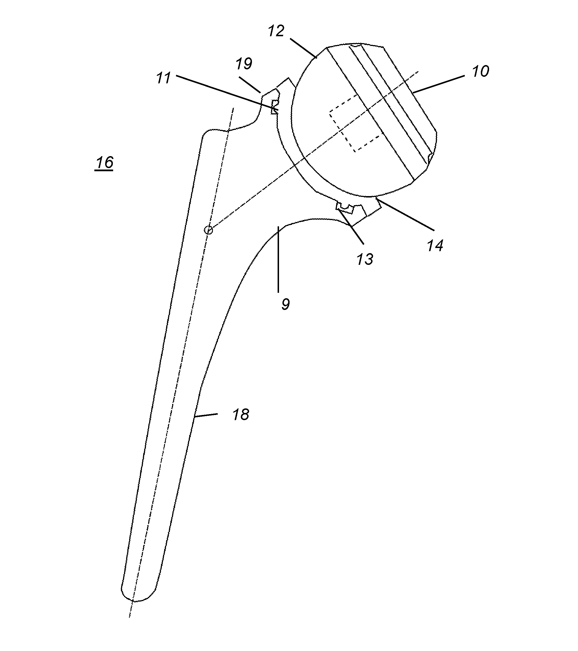
[0048]Referring to the Figures, wherein like numerals indicate like parts throughout the several views, attention is first directed to FIG. 1 in which is shown the inventive hip replacement implants as they would articulate in the human hip joint. The femoral component 16 comprises a femoral stem 18, shown in FIG. 1, which would be placed into the human femoral canal and the cup portion 19, shown on FIG. 1, which accepts a saucer shaped spacer 14. The femoral component 16 and spacer 14 replaces the femoral neck and head of a human hip. FIG. 1 shows the femoral component 16 with a shaft 18 to neck 9 angle of 140 degrees. This femoral component shaft to neck angle may vary from 120 to 140 de...


PUM


Abstract

A reverse total hip prosthesis is characterized by a femoral cup component and an acetabular ball component and is used for reconstruction of a hip joint. The prosthesis reverses the mechanics across the joint medializing the center of rotation, preventing dislocation in a posterior direction. Both ball and socket portions of the components lie outside of bone enabling larger sizing of the femoral and acetabular components improving stability, regardless of the size of the patient's anatomy. A method for reverse hip prosthesis implantation eliminates reaming through the base of the acetabulum preserving acetabular bone stock.

Description

CROSS-REFERENCE TO RELATED APPLICATION[0001]The present application claims the benefit of U.S. Provisional Application No. 62 / 282,472 filed Aug. 03, 2015 in the name of Nicholas J. Loffredo.FIELD OF THE INVENTION[0002]The invention relates generally to a hip replacement arthroplasty with the reversal of the traditional components. More specifically, the invention relates to a reverse total hip replacement with a femoral component that has a cup shaped articulating surface and an acetabular component that is characterized as a spherical segment having a spherical articulating surface portion.BACKGROUND OF THE INVENTION[0003]In regards to total hip arthroplasties Themistocles Gluck attempted the first hip femoral head arthroplasty with ivory implants in 1891 (Brand, Mont, & Manring, 2011). Since that time the total hip replacement has undergone a continually evolving spectrum of advancements in medical science. The evolution of the total hip replacement has led components to become st...

Claims


Application Information

Patent Timeline
Patent Type & Authority Applications(United States)
IPC IPC(8): A61F2/34A61F2/46A61F2/36
CPCA61F2/34A61F2/3609A61F2002/3615A61F2002/3483A61F2/4609A61B17/1666A61B17/1746A61B17/86A61F2/3603A61F2002/30332A61F2002/305A61F2002/30878A61F2002/4629A61F2002/4687
Inventor LOFFREDO, NICHOLAS JOHN
Owner LOFFREDO NICHOLAS JOHN
Why Eureka
Try Eureka