Eyeglass frame

a frame and eyeglass technology, applied in the field of eyeglass frames, can solve problems such as potential pain risk, and achieve the effect of reducing wear consciousness and eliminating any risk of pain on the user's head

Inactive Publication Date: 2010-05-25
FOUR NINES
View PDF4 Cites 5 Cited by
  • Summary
  • Abstract
  • Description
  • Claims
  • Application Information

AI Technical Summary

Benefits of technology

[0008]According to the present invention, a temple that is arranged to be foldable inwardly from the predetermined unfolded position is joined via elastic body so that the whole temple is capable to be displaced. Owing to this arrangement, only small contacting force is applied to the user's head and hence wearing consciousness is reduced. Thus, the present invention provides an eyeglass frame that has no potential risk of pain on the user's head.
[0009]According to the present invention, a temple that is arranged to be foldable inwardly from the predetermined unfolded position is connected to one end of an elastic body, while the other end of which is fixed with the front frame so that the whole temple is capable of being displaced. Thereby an end cover connected to the temple contacts with the head of user via a flat face so that small amount of contacting force is applied against the head of user. Thus, the present invention provides an eyeglass frame that gives less wearing consciousness and has no potential risk of pain on the head.
[0015]Accordingly, when temples are expanded, not only the temples are deformed but the whole temples can be displaced in the direction of expanding by means of the elastic body. In addition, the front frame made of metal or plastic can be slightly expanded so that inside surface of the end cover provided on the temple comes to contact with the head of a user via flat face. Thereby, contacting force on the user's head becomes smaller to reduce wearing consciousness, resulting in eliminating any risk of pain on the user's head while wearing.

Problems solved by technology

In a conventional eyeglass frame as described above, however, the optimum condition for users is intended to be secured by adjusting mainly the temple bending curvature, which causes such a problem that temple adjustment affects armor portion attached to the rim since the temple is integrated with the armor.
Due to this fact the adjustment comes to a result that apart of inside surface of the temple contacts with a point of user's head and the contacting force with the head becomes big, which causes a problem of potential risk of pain.

Method used


Image

  • Eyeglass frame
  • Eyeglass frame
  • Eyeglass frame

Examples


first embodiment

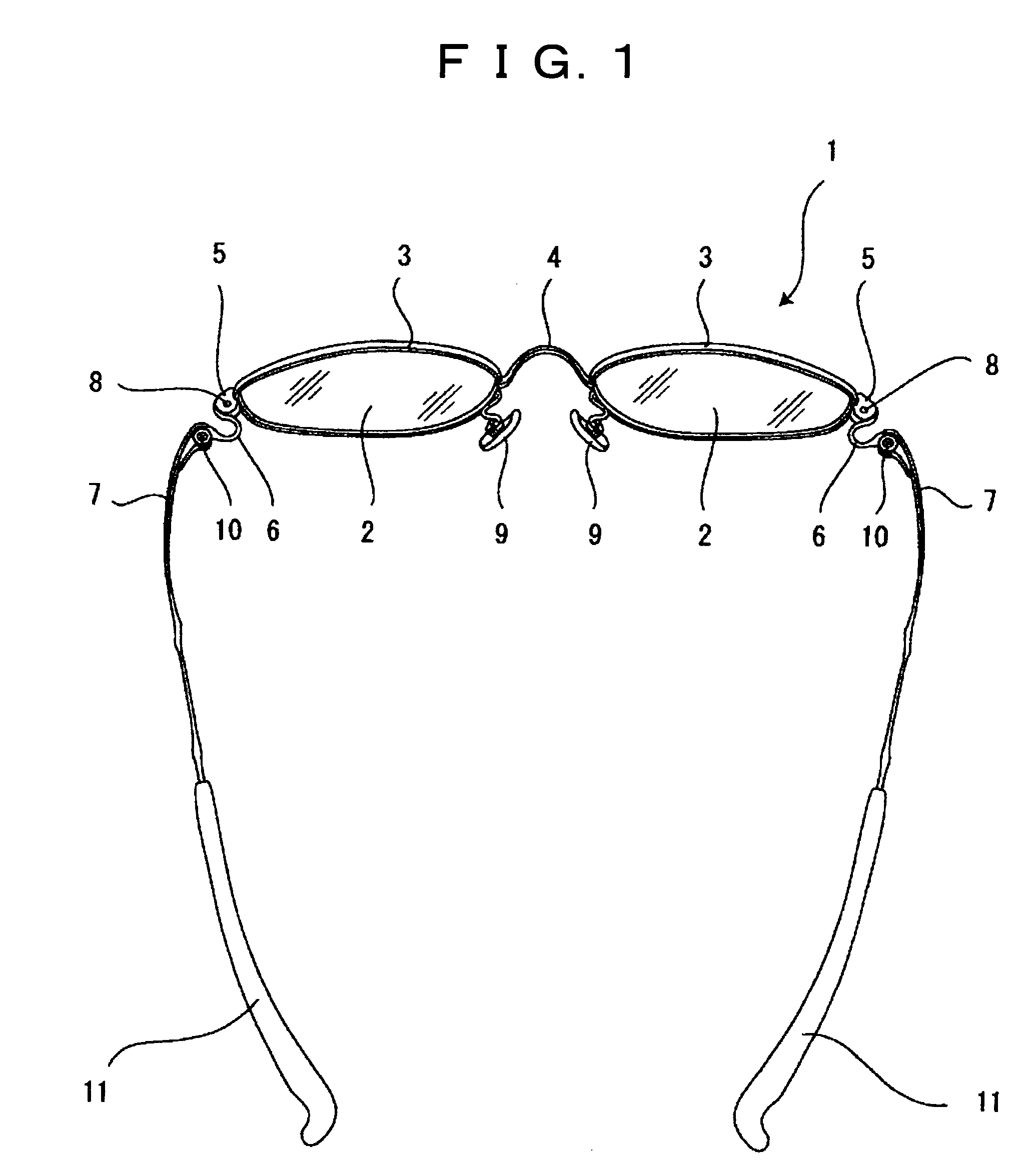
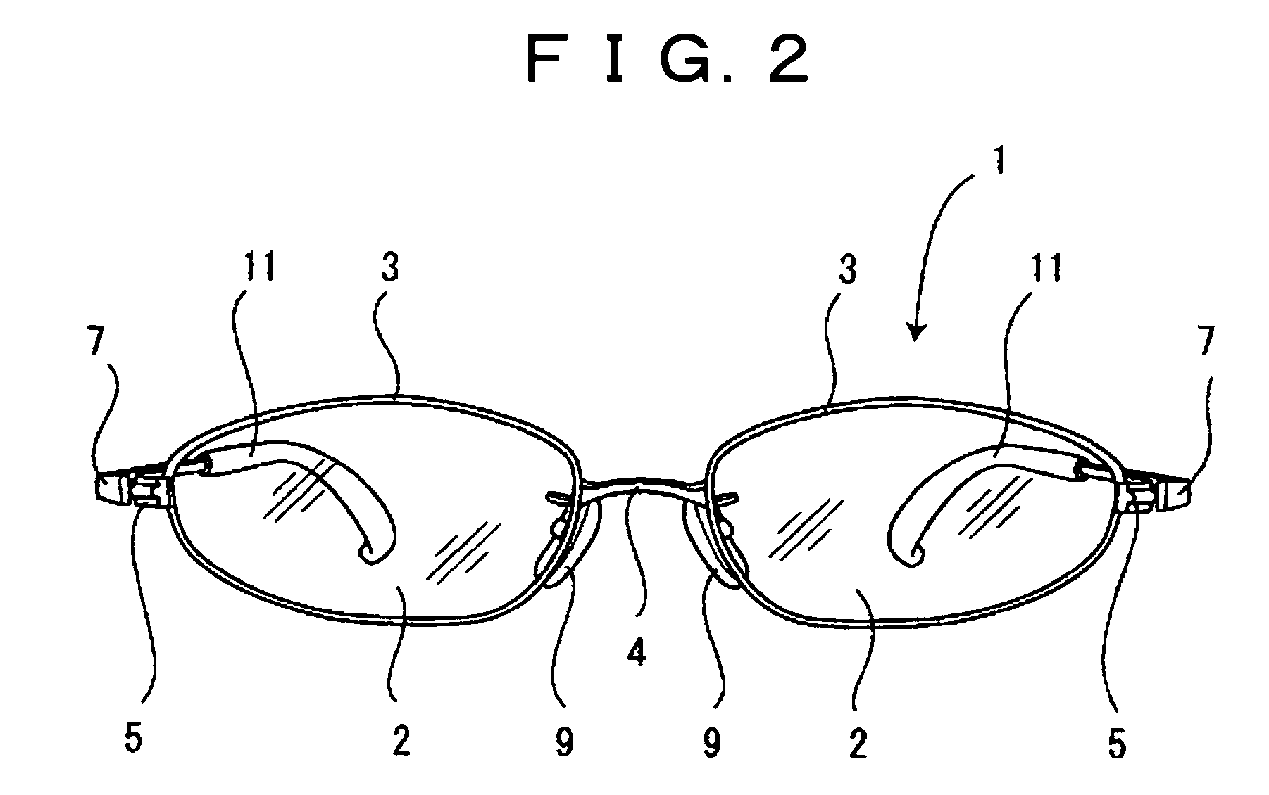
[0024]FIG. 1 is a plan view of an eyeglass frame 1 showing the present invention, FIG. 2 is a schematic front view thereof, and FIG. 3 is a schematic view observed from diagonally above. In addition, FIG. 4 is a schematic view showing connection condition of a front frame, an elastic body and a temple.

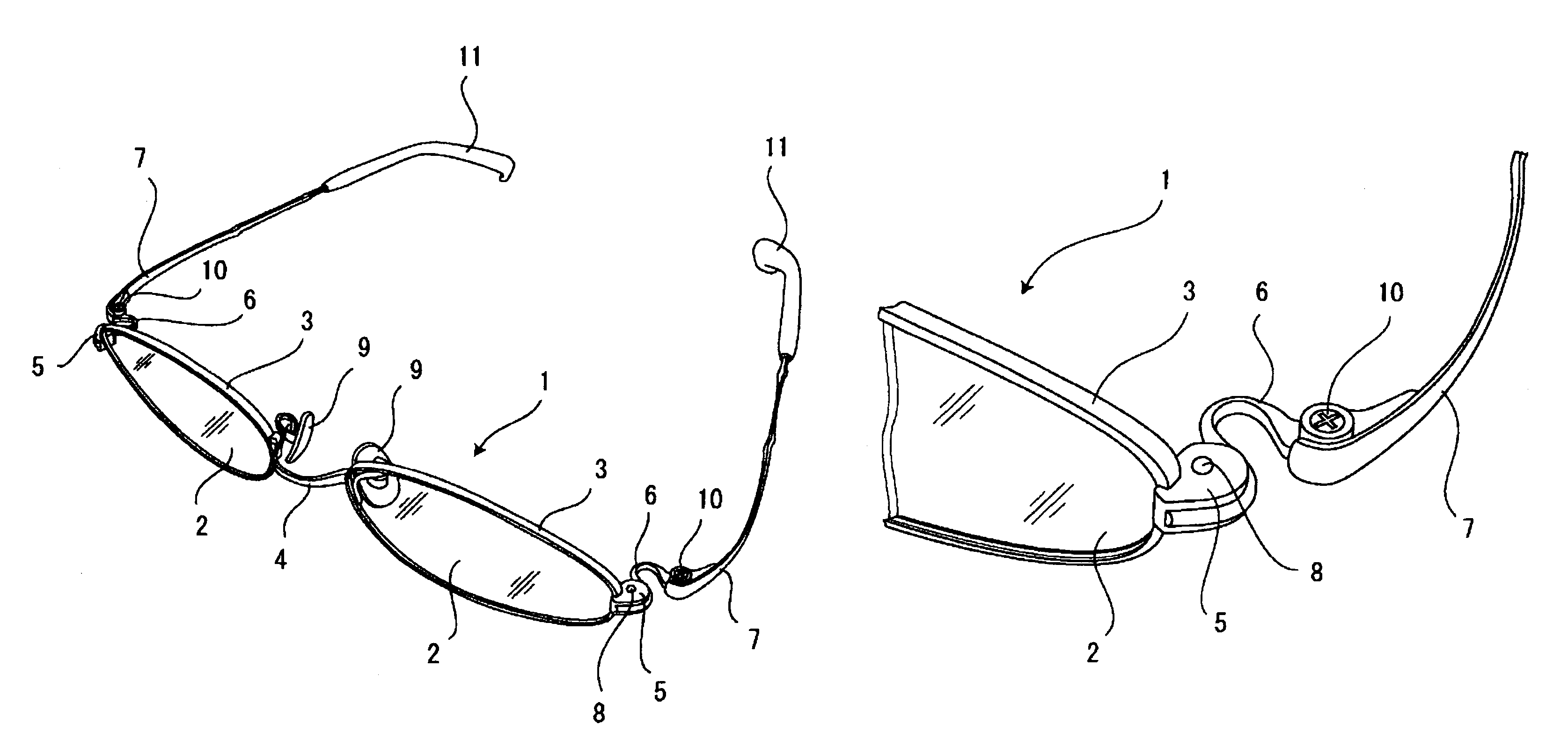
[0025]The eyeglass frame 1 is a full rim type eyeglass frame made of metal and a pair of lenses 2, 2, left and right, are fitted thereto, the eyeglass frame 1 including rims 3, 3 forming a front frame which is joined at a bridge portion 4, armor portions 5, 5 disposed at the outer side of the rims 3, 3 which nip and release perimeter of the lenses 2, 2 when exchanging the lenses 2, 2 or doing the like, elastic bodies 6, 6 connected to the armor portions 5, 5, and the temples 7, 7 which are connected to the elastic bodies 6, 6 and nip the head of users above the ears thereof while pressing the same.

[0026]Screws 8, 8 are provided on the armor portions 5, 5 of the both sides of the rims. ...

second embodiment

[0036]FIG. 5 to FIG. 7 show eyeglass frame according to the present invention, and FIG. 5 is a schematic plan view of an eyeglass frame 21, FIG. 6 is a schematic front view, and FIG. 7 is a schematic view observed from diagonally above.

[0037]This eyeglass frame is made of plastic, being of full rim type, to which a pair of lenses 22, 22, left and right, are fixed, including a front frame 23 provided with a bridge 24 at the central portion, elastic bodies 25, 25 disposed at the both outer end sides on the rear face of the front frame 23, and the temples 27, 27 provided at the opposite sides of the front frame 23 in the elastic bodies 25, 25 via the hinges 26, 26 and is arranged to press user's head above the ears to nip the same position.

[0038]The elastic bodies 25, 25 provided on both sides of the front frame 23 are fixed to both outer side ends of the front frame 23 by embedding embedding portions 28, 28 provided at one end of the elastic bodies 25, 25 into the outer side ends of t...


PUM


Abstract

An eyeglass frame is formed so as to eliminate pain to a wearer when the frame nips the head of the wearer for a long period of usage. The eyeglass frame includes a front frame made of plastic or metal for holding lenses, a pair of elastic bodies, a first end of each elastic body is attached to either side of a rear face of the front frame and is bent inwardly at a central portion thereof, and a temple disposed at a second end of each elastic body. The temple has an end cover. One of the first end and the second end of the elastic body is connected to a hinge.

Description

BACKGROUND OF THE INVENTION[0001]1. Field of the Invention[0002]The present invention relates to an eyeglass frame on which temples are attached via elastic bodies on both sides of the rear face of a front frame which holds lenses.[0003]2. Description of the Related Art[0004]Generally, in a front frame of eyeglass, there are such types as a full rim type as described in JP, A, 2003-43427, or a half rim type. A pair of temples that contact with side faces of users' head are provided on both sides of the rear face of the rim that is for installing lenses so as to be rotatable inwardly and foldable from the predetermined expanded condition.[0005]In usual eyeglass frames arranged as described above, users use an eyeglass in such a way that the temples nip the user's head at both sides of ears in a condition where the temples are rotated fully outwardly to come to an end. Further, temple bending curvature is mainly adjusted so that a user can be released from tightness while wearing eyeg...

Claims


Application Information

Patent Timeline
Patent Type & Authority Patents(United States)
IPC IPC(8): G02C3/00
CPCG02C3/003G02C5/10G02C5/2254Y10T16/526G02C2200/22
Inventor MIKAME, TETSUO
Owner FOUR NINES
Why Eureka
Try Eureka