
Oversampled channel response identification
a technology of impulse response and data channel, applied in the field of identification of impulse response of oversampled data channel, can solve the problems of inability to achieve simple approach, inability to achieve equalization, and inability to solve simple approach, etc., to achieve high-speed, efficient, and mitigate the effect of noise in output signals
- Summary
- Abstract
- Description
- Claims
- Application Information
AI Technical Summary
Benefits of technology
Problems solved by technology
Method used
Image

Examples
Embodiment Construction
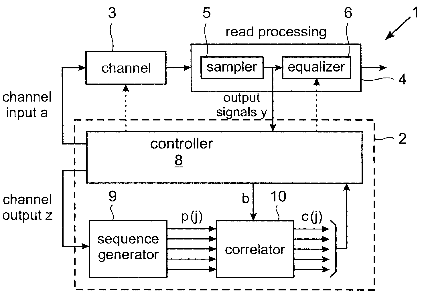
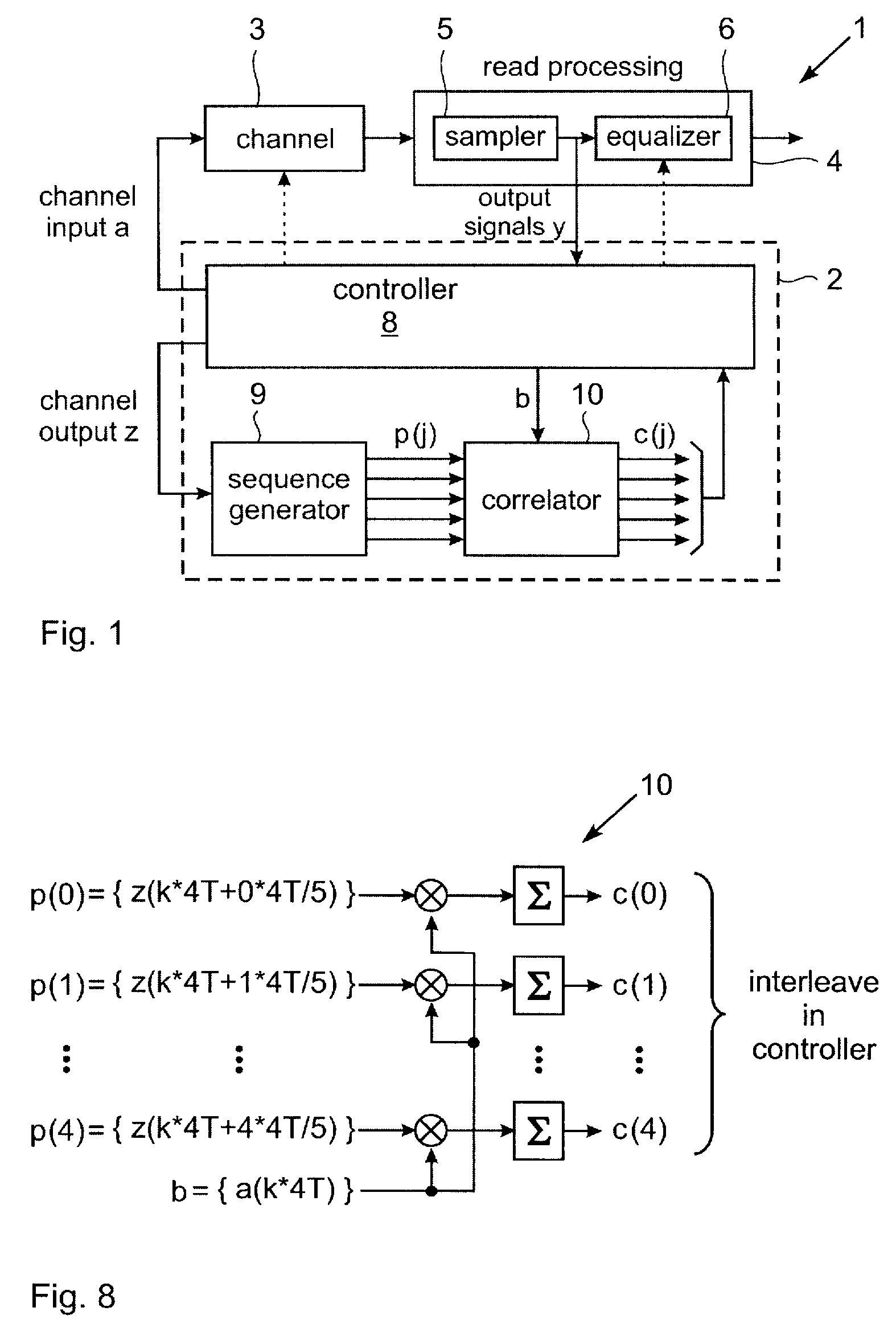
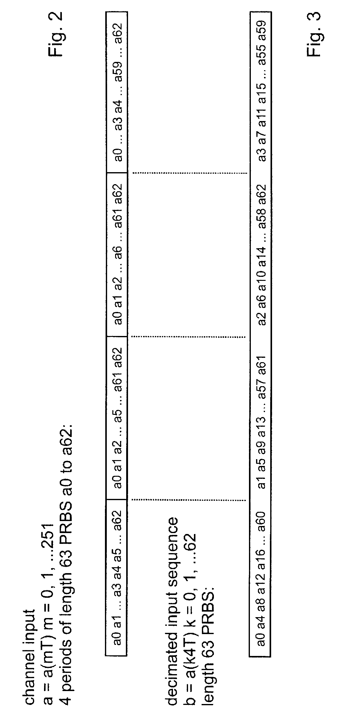
[0042]A data storage system incorporating an embodiment of impulse response identification apparatus is illustrated schematically in FIG. 1. In this example, the data storage system is a tape drive 1 and includes impulse response identification apparatus in the form of response analysis module 2 which implements a response identification method embodying the invention. The data channel here is thus a magnetic recording channel 3 comprising a read / write head for recording data on, and reading data from, a magnetic tape. In operation of tape drive 1, data is recorded in channel 3 with a recording data rate of 1 / T. Readback signals output by the read / write head are supplied to read processing apparatus indicated generally at 4. Read processing apparatus 4 is shown in simplified form in the figure as including a sampler 5 and an equalizer 6 to which particular reference will be made in describing operation of response analysis module 2. Sampler 5 samples readback signals output by chann...
PUM
 Abstract
Description
Claims
Application Information