Oversampled Channel Response Identification

a technology of impulse response and data channel, applied in the field of identification of impulse response of oversampled data channel, can solve the problems of inability to achieve simple approach, inability to achieve equalization, and inability to solve simple approach, etc., to achieve high-speed, efficient, and mitigate the effect of noise in output signals

Inactive Publication Date: 2008-06-12
IBM CORP
View PDF5 Cites 7 Cited by
  • Summary
  • Abstract
  • Description
  • Claims
  • Application Information

AI Technical Summary

Benefits of technology

[0013]Thus, in embodiments of the invention, p polyphase sequences are produced from an oversampled channel output corresponding to the input PRBS. Each of these polyphase sequences is correlated with a PRBS produced by decimating the original input PRBS by q, with the two possible bit values being of equal and opposite magnitude, effectively ±1, for the correlation process. Correlation of two signals essentially involves multiplication of samples of one signal with respective corresponding samples of the other signal. In the process just described, the correlation process involves a change of sign. The multiplication of real numbers, and hence the need for true multipliers, is therefore avoided. Nevertheless, when the results of correlating the polyphase sequences with the decimated sequence are interleaved, the process yields the impulse response of the data channel. An elegantly simple and highly efficient process is therefore provided for multiplication-free identification of the oversampled channel impulse response. Embodiments of the invention offer efficient, high-speed implementations in both hardware and software, and can be employed to advantage in any of the various applications, both online and off-line, which rely on identification of the channel impulse response.
[0014]Clearly if the data channel is a magnetic recording channel then the input PRBS will be recorded in the recording channel. In this case the impulse response produced is the pulse, or dibit, response of the recording channel. In other embodiments the data channel may be a wired or wireless communications channel in which case the input PRBS is of course transmitted over the channel. In either case, the channel output from which the polyphase sequences are generated is preferably produced by averaging a plurality of sampled channel output signals corresponding to the input PRBS. This averaging process mitigates the effects of noise in the output signals. The recorded PRBS will thus be read a plurality of times in recording applications, and the input PRBS will be transmitted and received a plurality of times in communications applications.
[0015]While the channel input could conceivably consist of a sole instance of the PRBS, better results can be achieved by employing a channel input comprising a periodic sequence, each period of which comprises the L-symbol PRBS. For greatest efficiency, the channel input preferably comprises q periods of the PRBS.
[0017]Embodiments of the invention may be employed for fast, accurate and efficient computation of various parameters of the channel output processing apparatus. Thus, an embodiment of a third aspect of the invention provides a method for determining one or more parameters of signal processing apparatus for processing output signals from a data channel, the method comprising identifying the response of the data channel by a method according to the first or second aspects of the invention, and processing the response to derive a value for each said parameter dependent on that response. A particularly useful application here is the computation of the equalizer coefficients using the channel impulse response.

Problems solved by technology

Nonlinear distortion cannot, in general, be corrected by equalization.
For oversampled waveforms, i.e. where the channel output signal is sampled at a higher rate than 1 / T, such a simple approach is not feasible.
Unfortunately, this method requires multiplication of real numbers, rendering its implementation in hardware or software impractical.

Method used


Image

  • Oversampled Channel  Response Identification
  • Oversampled Channel  Response Identification
  • Oversampled Channel  Response Identification

Examples


Embodiment Construction

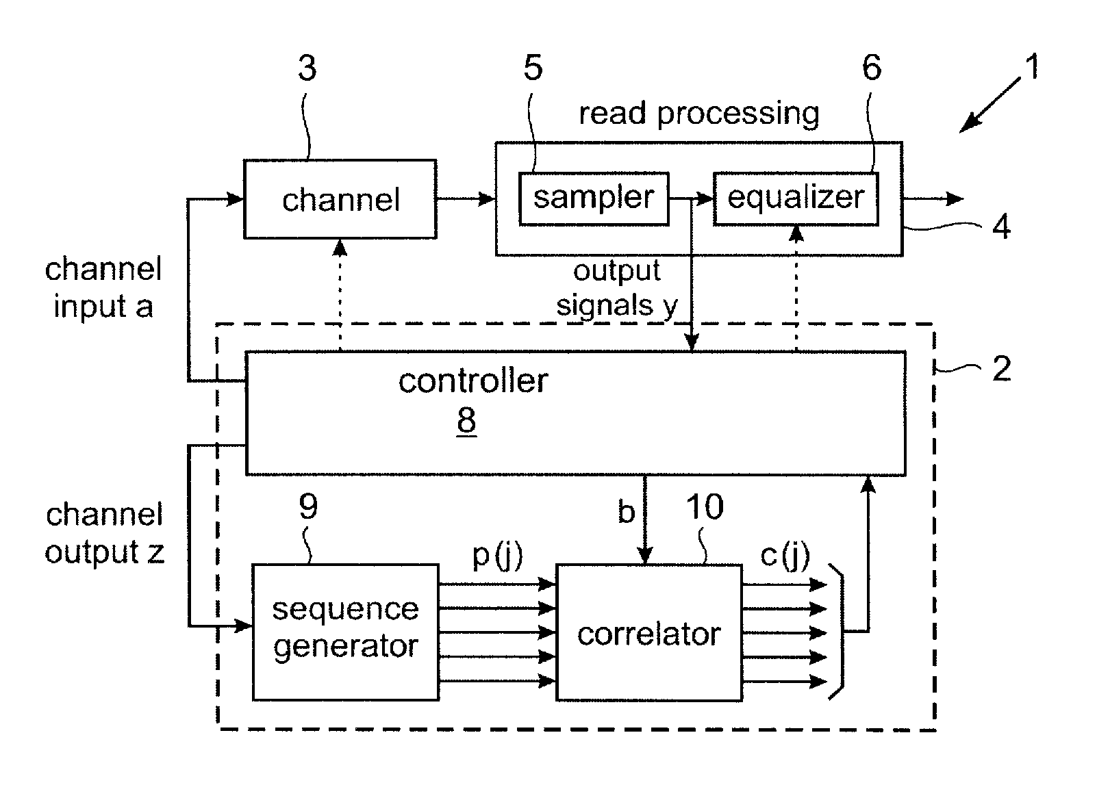
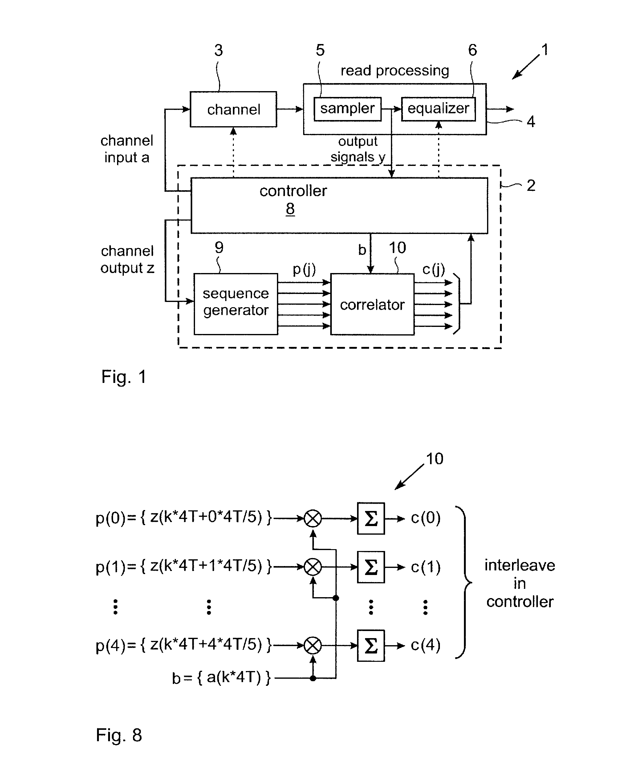
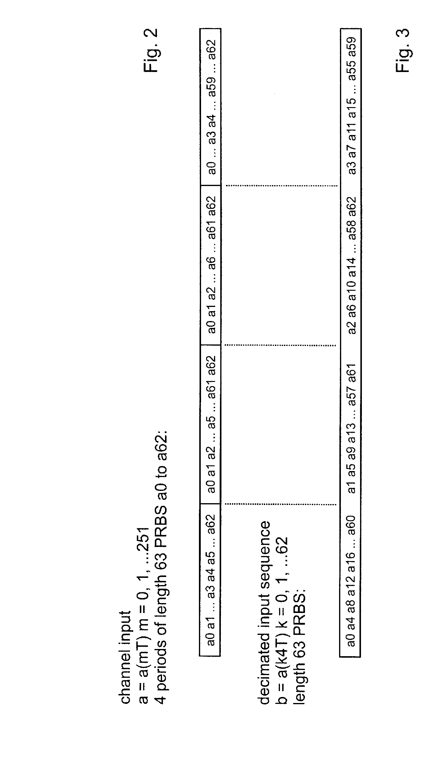
[0042]A data storage system incorporating an embodiment of impulse response identification apparatus is illustrated schematically in FIG. 1. In this example, the data storage system is a tape drive 1 and includes impulse response identification apparatus in the form of response analysis module 2 which implements a response identification method embodying the invention. The data channel here is thus a magnetic recording channel 3 comprising a read / write head for recording data on, and reading data from, a magnetic tape. In operation of tape drive 1, data is recorded in channel 3 with a recording data rate of 1 / T. Readback signals output by the read / write head are supplied to read processing apparatus indicated generally at 4. Read processing apparatus 4 is shown in simplified form in the figure as including a sampler 5 and an equalizer 6 to which particular reference will be made in describing operation of response analysis module 2. Sampler 5 samples readback signals output by chann...


PUM


Abstract

Methods, apparatus and computer programs are provided for multiplication-free identification of the impulse response of an oversampled data channel. An input comprising a pseudo-random binary sequence of L symbols is supplied to the channel at a symbol rate of 1 / T. A channel output is produced by sampling a channel output signal corresponding to the input with a sampling interval TS=(q / p)T, where q and p are relative prime integers with q<p, and q and L are relative prime integers. p polyphase sequences are produced from the channel output by selecting, for each polyphase sequence, every pth sample of the channel output, with a phase shift of one sample between successive polyphase sequences). A decimated binary sequence is produced by selecting every qth symbol of the channel input. Each polyphase sequence is correlated with the decimated binary sequence, the two possible binary values being of equal magnitude and opposite sign for the correlation. The correlation results are accumulated to produce a correlated output sequence for that polyphase sequence. The samples of the correlated output sequences are then interleaved in phase order of the corresponding polyphase sequences to produce the impulse response of the channel.

Description

FIELD OF THE INVENTION[0001]This invention relates generally to identification of the impulse response of an oversampled data channel. Methods, apparatus and computer programs are provided for identifying the impulse response, and for determining additional parameters such as equalizer coefficients which are dependent on the response.BACKGROUND OF THE INVENTION[0002]The impulse response of a data channel such as a communications or magnetic recording channel is important for determining parameters of various media and signal processing components. In magnetic recording, where non-return to zero (NRZ) modulation format is usually adopted, the impulse response of the recording channel corresponds essentially to the pulse, or “dibit”, response, i.e. the response of the channel to a pulse input. The step, or “transition”, response of the recording channel, i.e. the response of the channel to a step input, can be derived from this dibit response. The dibit and transition responses of the...

Claims


Application Information

Patent Timeline
Patent Type & Authority Applications(United States)
IPC IPC(8): H04L27/01H04L27/00
CPCG11B20/10009G11B20/10046G11B20/10212H04L25/03038H04J2013/0037H04L25/0212H04B1/7085G11B20/14G11B20/10G11B5/02
Inventor CHERUBINI, GIOVANNIELEFTHERIOU, EVANGELOS S.HUTCHINS, ROBERT ALLENJAQUETTE, GLEN ALANOELCER, SEDAT
Owner IBM CORP
Why Eureka
Try Eureka