Disposable dental handpiece

a technology of handpieces and hand plates, applied in the field of handpieces, can solve the problems of assembly imperfections, difficulty in passageways or conduits for light, air and/or water, etc., and achieve the effect of high speed and efficient operation

Active Publication Date: 2012-07-03
MURPHY DAVID +2
View PDF142 Cites 2 Cited by
  • Summary
  • Abstract
  • Description
  • Claims
  • Application Information

AI Technical Summary

Benefits of technology

[0009]An aspect of at least one of the embodiments disclosed herein includes the realization that dental handpieces can be run with air, and that incorporating a structure which delivers air to the turbine blades of the handpiece in an efficient and high speed manner is advantageous.
[0011]Another aspect of at least one of the embodiments disclosed herein includes the realization that sealing two shell halves and a core together to form various conduits or passageways for light, air, and / or water can be difficult, and can lead to imperfections in the assembly. Including tapered mating portions on the core and left shell half can provide a gradually changing distance from the surface of the core for welding, thereby reducing or eliminating shape changes sufficiently sharp to cause imperfections in a sonic welding assembly.
[0013]Another aspect of at least one of the embodiments disclosed herein includes the realization that it is advantageous for dental instruments to direct light to a patient's tooth or interaction region, so as to better view what work is being done. Thus, it is desirable to have a reliable, stable light source attached to and within the dental handpiece to deliver light from the handpiece.
[0015]Another aspect of at least one of the embodiments disclosed herein includes the realization that directing air to a turbine within the dental instrument can be made more efficient through the use of a flow deflector. The geometry of the flow deflector can increase air speed, reduce noise, and direct the air flow in a particular manner within the turbine area of the handpiece.
[0017]Another aspect of at least one of the embodiments disclosed herein includes the realization that reducing the weight of a dental handpiece can save on cost, as well as make the handpiece easier to ship and use.

Problems solved by technology

Another aspect of at least one of the embodiments disclosed herein includes the realization that sealing two shell halves and a core together to form various conduits or passageways for light, air, and / or water can be difficult, and can lead to imperfections in the assembly.

Method used


Image

  • Disposable dental handpiece
  • Disposable dental handpiece
  • Disposable dental handpiece

Examples


Embodiment Construction

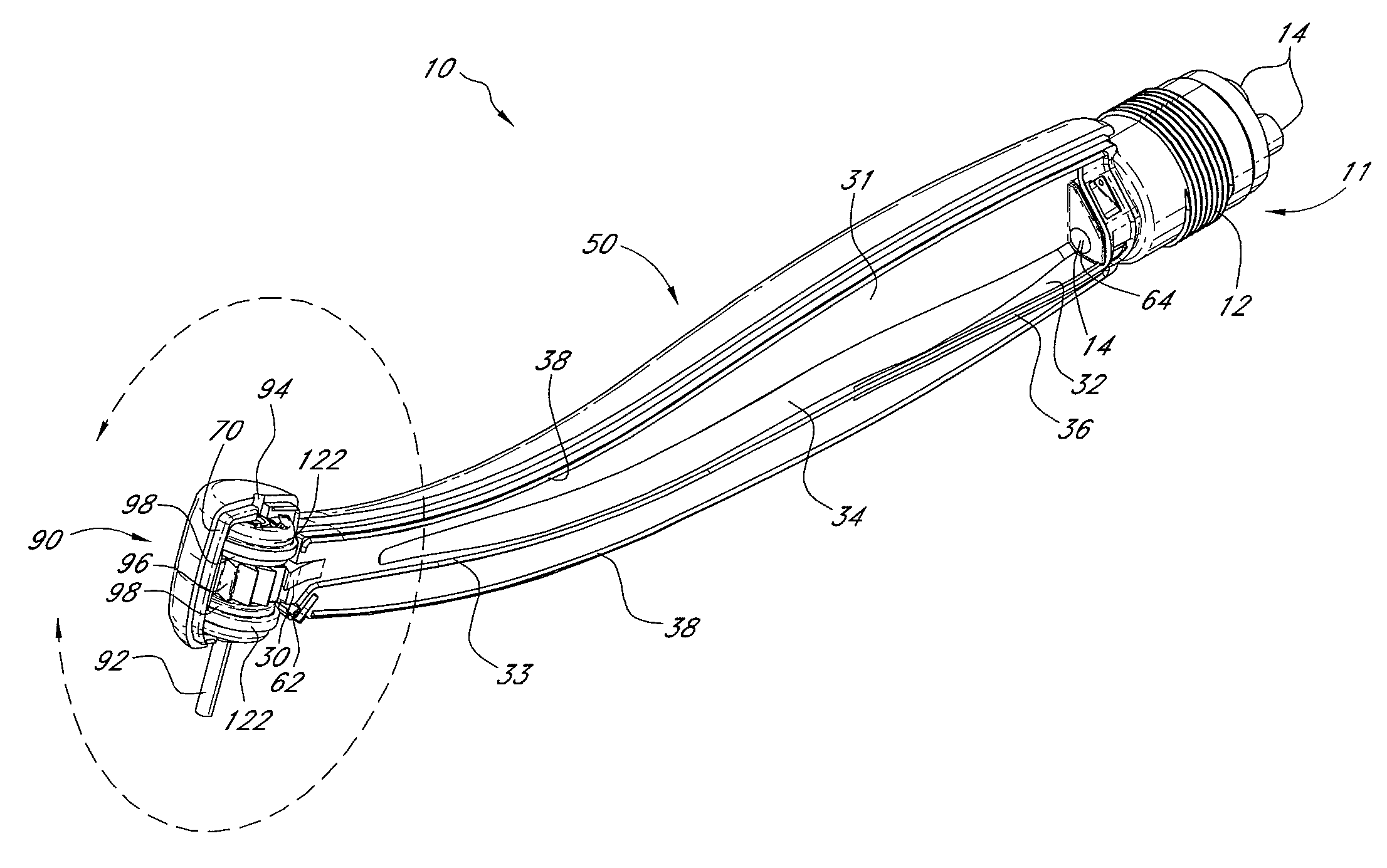
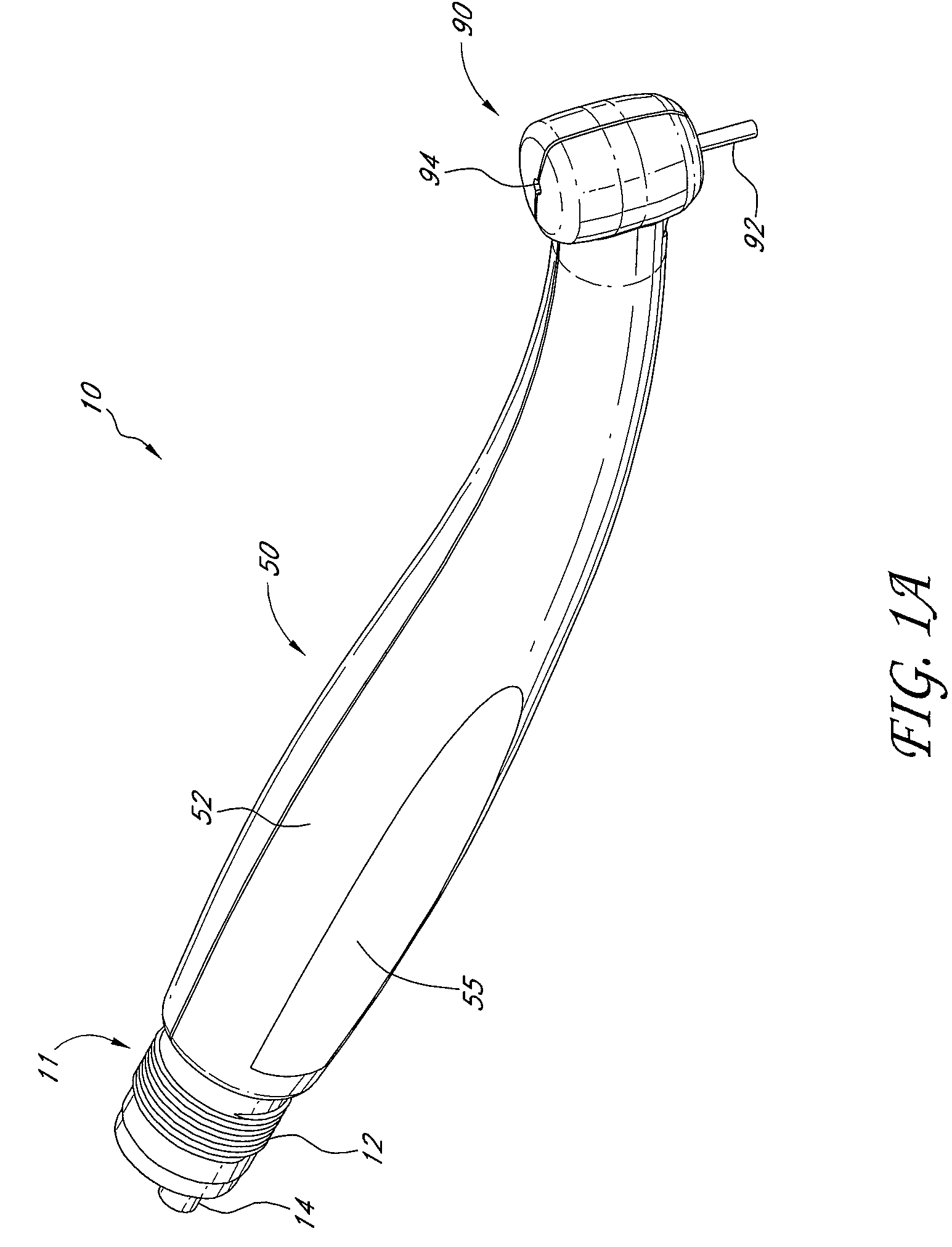
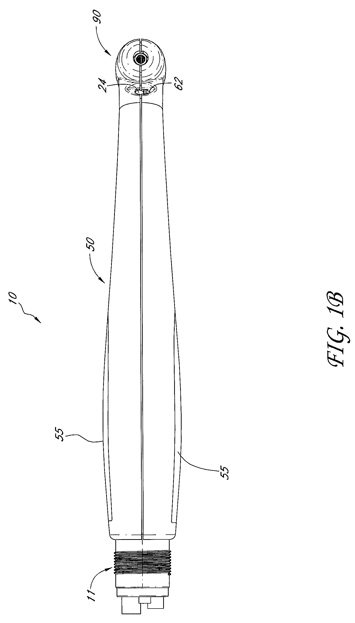
[0051]With reference to FIG. 1A, an embodiment of the handpiece 10 generally includes a base 11, body 50, and head 90. The handpiece 10 is advantageously sized to fit comfortably in the human hand. The handpiece 10 can be connected to a source of various fluids under pressure, including but not limited to air and water. A light source can also be connected to the handpiece 10. Light from the light source can be directed by means of a light pipe to illuminate an interaction region on or near a patient's tooth. During operation, an operator controllably introduces pressurized air into a first portion of the handpiece 10, shaped to direct the air to a turbine in the head 90. The turbine, having both impeller blades and a shaft coupled to a drill bit, is turned by the pressurized air, causing the drill bit to rotate at high speeds. Preferably, the drill speeds are useful for dental procedures. By controlling the supply of pressurized air to the handpiece 10, the speed of the drill can b...


PUM


Abstract

A sterile, substantially maintenance free disposable dental handpiece is constructed from two shells and a center core, the center core having a flow deflector on one end. The shells are joined around the core with mating protrusions and / or tapered walls to form the body and head of the handpiece. A base is integrally-formed with the center core. The base has conduits that allow entry of light and pressurized air and / or water into the body. The head at the opposite end of the body from the base rotatably mounts an impeller assembly having an impeller shaft. The impeller shaft includes blades driven by the pressurized air. The blades can have cavities to reduce weight.

Description

[0001]This application is a non-provisional of and claims benefit under 35 U.S.C. §119(e) to U.S. Provisional Patent Application No. 60 / 969,094, filed Aug. 30, 2007, which is incorporated in its entirety by reference herein.BACKGROUND OF THE INVENTION[0002]1. Field of the Invention[0003]The present invention relates generally to a handpiece for dental procedures, and more particularly to a disposable hand-held instrument for dental drilling.[0004]2. Background[0005]Common dental procedures involve the use of a drill to reduce at least a portion of a tooth prior to performing work on the area of the mouth on or near the tooth. In some instances, decayed enamel is removed from a tooth prior to replacement with a hardened substitute. In some instances, some or all of a tooth is removed with a dental drill prior to work beneath the gum line.[0006]Typical drills used for such work have several components. First, a handpiece, typically constructed from stainless steel, or a steel alloy is...

Claims


Application Information

Patent Timeline
Patent Type & Authority Patents(United States)
IPC IPC(8): A61C1/05A61C1/08
CPCA61C1/05A61C1/16A61C1/08Y10S415/904
Inventor THOMSSEN, ELISCHIPPER, DIRKTURNER, KEVIN
Owner MURPHY DAVID
Why Eureka
Try Eureka