Method of mounting a transducer to a driveshaft

Inactive Publication Date: 2010-07-27
BOSTON SCI SCIMED INC
View PDF28 Cites 0 Cited by
  • Summary
  • Abstract
  • Description
  • Claims
  • Application Information

AI Technical Summary

Benefits of technology

[0008]A further separate aspect of the invention involves a method of making a transducer mounting to a driveshaft comprising a step of treating the distal tip of the driveshaft by hardening the distal tip with a soldering process, wherein the driveshaft is made of flexible wound wires having interstices therebetween and the soldering process fills the interstitial spaces such that a rigid distal tip is formed. This method optionally contemplates the use of a cold clamp having a high specific heat to dissipate excess heat during soldering. In addition, this method may incorporate the use of a ceramic or fiber-optic plug for keeping the central lu

Problems solved by technology

In addition, the joint created between the driveshaft

Method used


Image

  • Method of mounting a transducer to a driveshaft
  • Method of mounting a transducer to a driveshaft
  • Method of mounting a transducer to a driveshaft

Examples


Example

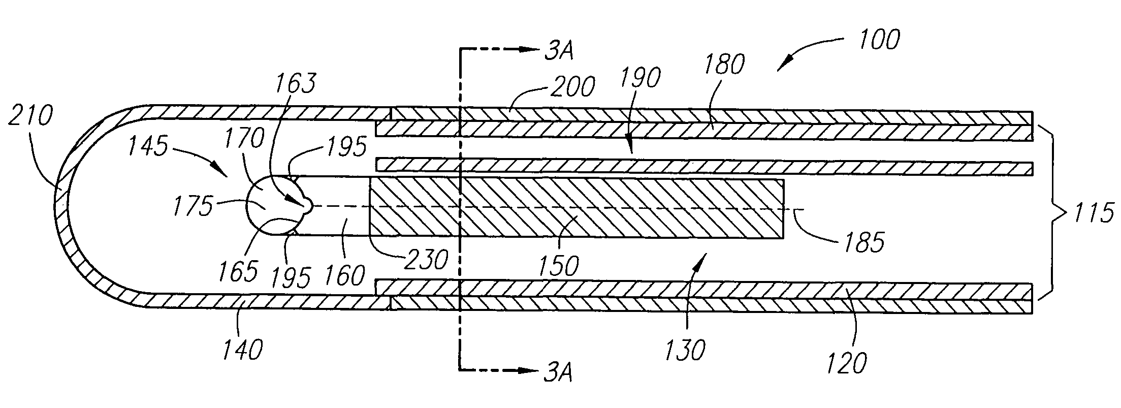
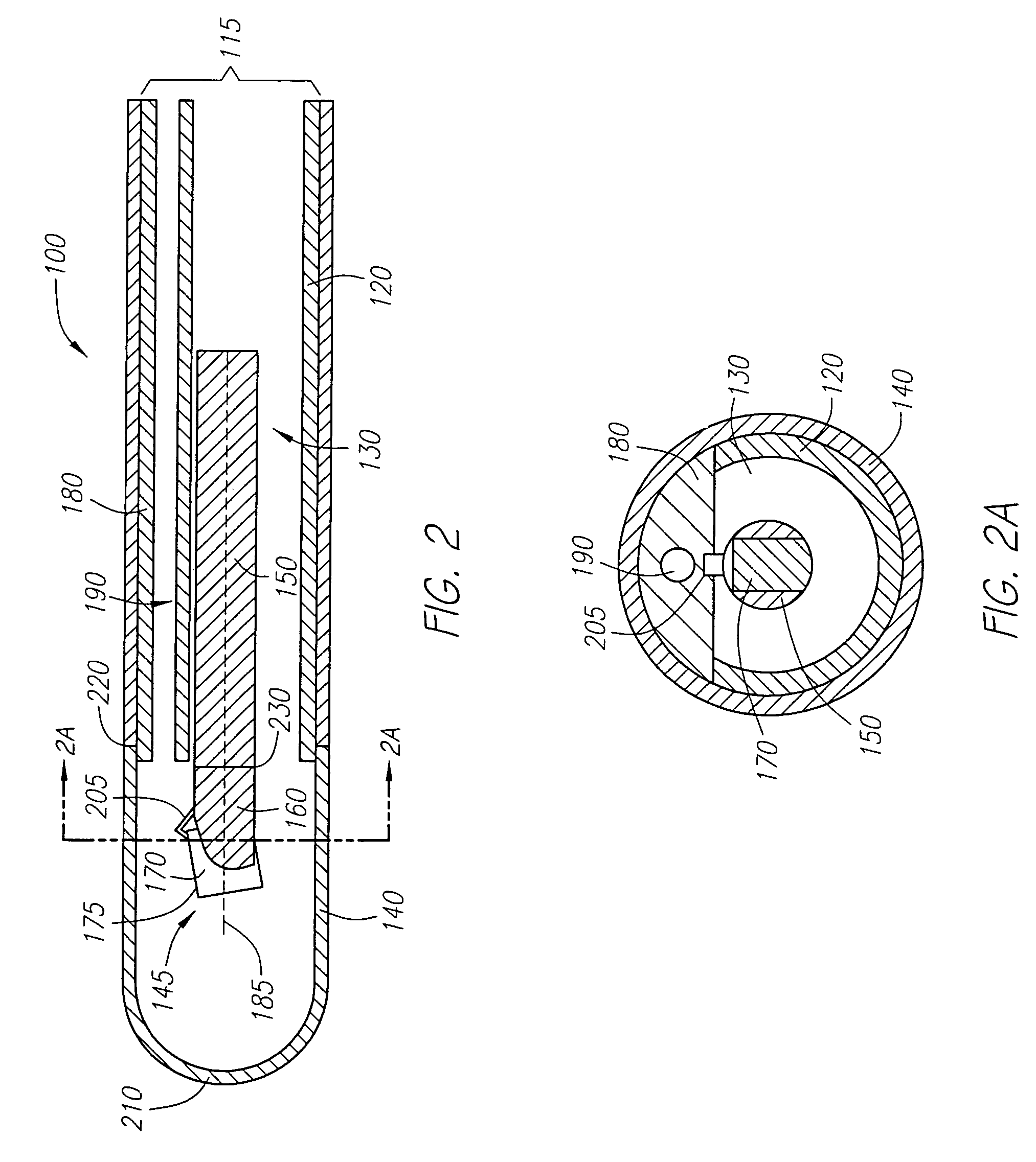
[0021]With respect to FIGS. 2 and 3, a preferred ultrasound catheter assembly 100 includes an elongate tubular element 115 having tubular section 120, which forms an axially disposed lumen 130. A dome-shaped acoustic imaging window 140 is attached to a distal end of the elongate tubular element 115, thereby forming an enclosed tip of the catheter assembly 100. Alternatively, the shape of the acoustic imaging window 140 may be virtually any shape or combination of shapes. An imaging core 145 comprising a flexible driveshaft 150 having a rigid distal tip 160 and a generally cylindrical transducer 170 is disposed within lumen 130. The imaging core 145 is capable of translation along its center axis 185.

[0022]As best seen in FIG. 2A, axially disposed lumen 130 has a substantially “D-shaped” cross-section wherein the inner dimensions of lumen 130 are sufficient for transducer 170 to be translated therein. With further reference to FIG. 2A, a solid section 180 of elongate tubular element ...


PUM


Abstract

A method of mounting a transducer to a driveshaft which eliminates the need for a transducer housing, the improved method directly attaches the transducer to a rigid distal tip of a driveshaft which is part of a rotatable imaging core of a catheter assembly. The method contemplates heat treating the distal tip of the driveshaft to make it rigid, machining the distal tip to be dimensioned to hold the transducer, and attaching the transducer to the distal tip by clamping, crimping, or an adhesive.

Description

PRIOR APPLICATIONS[0001]This application is a divisional of U.S. patent application Ser. No. 09 / 755,873, filed on Jan. 4, 2001 now abandoned.FIELD OF THE INVENTION[0002]The present invention relates, in general, to transducer mountings for ultrasound catheter assemblies used in diagnostic or therapeutic applications.DISCUSSION OF RELATED ART[0003]Mechanically scanned ultrasound catheter assemblies employ a single transducer mounted inside a rotating housing. In particular, the transducer transmits and receives ultrasonic waves while the transducer housing rotates about a fixed axis in an acoustic window located at a distal tip of the catheter. The rotational motion of the transducer housing is accomplished by a flexible driveshaft that extends through an axially disposed lumen of the catheter, wherein the driveshaft has one end connected to the transducer housing. Once the distal end of the catheter is positioned, for example, in a patient's vascular system, a cross-sectional image ...

Claims


Application Information

Patent Timeline
IPC IPC(8): A61B8/00A61B8/12
CPCA61B8/12A61B8/445A61B8/4461
Inventor SERRANO, MANUELKOGER, JAMES D.
Owner BOSTON SCI SCIMED INC
Why Eureka
Try Eureka