Method and apparatus for an action system for a firearm

a technology of action system and firearm, applied in the field of firearms, can solve the problems of non-lethal projectiles, non-lethal weapons, disproportionately bulky mechanisms, etc., and achieve the effect of low maintenance and reliabl

Active Publication Date: 2010-08-10
SNAKE RIVER MACHINE
View PDF12 Cites 10 Cited by
  • Summary
  • Abstract
  • Description
  • Claims
  • Application Information

AI Technical Summary

Benefits of technology

[0006]The present invention is a roller-lock delayed blowback mechanism providing a compact, low-maintenance, reliable, and lightweight action system for a firearm, preferably a semi-automatic shotgun. A primary roller-lock mechanism is located to the rear of the feeding and ejecting ports of the firearm and preferably contained within the approximate diameter of a cartridge.
[0007]An alternative embodiment of the present invention further incorporates a secondary, or compounding, roller-lock mechanism within the action system to further delay the opening of the firearm chamber. This is advantageous because locating the locking rollers to the rear of the ejection port obviates the use of a relatively long and proportionately heavy bolt in which the rollers are caged. Thus, a relatively lighter bolt carrier—to be accelerated past inwardly pinching rollers—provides less inertial resistance to the accelerating force than prior conventional designs wherein the bolt carrier is proportionately larger, heavier, and more resistant to acceleration. That is, the reduced delaying effect of the primary roller-lock mechanism brought about by the necessarily diminished physical space requirements, has been increased by compounding the primary roller-lock mechanism rather than by adding mass. In the preferred embodiment, the inertia of a relatively lesser mass (the firing pin and striking hammer) sufficiently delays the opening of the firing chamber until the explosive pressure within is reduced to a safe level by retarding the movement of the bolt carrier relative to the bolt, which in turn retards the movement of the bolt relative to the barrel and receiver of the shotgun. The compounding or additional stage of roller-lock delay is increased similar in effect to compounding a 1:10 gear ratio to produce a 1:100 ratio.
[0011]A still further aspect of the present invention is directed to a method for delaying movement of a bolt in response to firing of the semi-automatic shotgun. The method includes: positioning a roller rearward of the ejection port; providing a resistance to rearward movement of the bolt in response to the firing of the semi-automatic shotgun; and, varying the resistance.

Problems solved by technology

This is likely because the large diameter of the cartridge would require a disproportionately bulky mechanism and would interfere with the space necessary for feeding and ejecting the cartridges when situated near the front of the bolt—as in all previous known designs.
In contrast, employing a constant or fixed amount of rearward resistance for use in a shotgun that is capable of firing a wide range of ammunition sizes and types—e.g., 2¾ inch light target loads, 3 inch magnum slug loads, non-lethal projectiles—does not work as well.

Method used


Image

  • Method and apparatus for an action system for a firearm
  • Method and apparatus for an action system for a firearm
  • Method and apparatus for an action system for a firearm

Examples


Embodiment Construction

[0027]While the present invention is susceptible of embodiment in many different forms, there is shown in the drawings and will herein be described in detail preferred embodiments of the invention with the understanding that the present disclosure is to be considered as an exemplification of the principles of the invention and is not intended to limit the broad aspect of the invention to the embodiments illustrated.

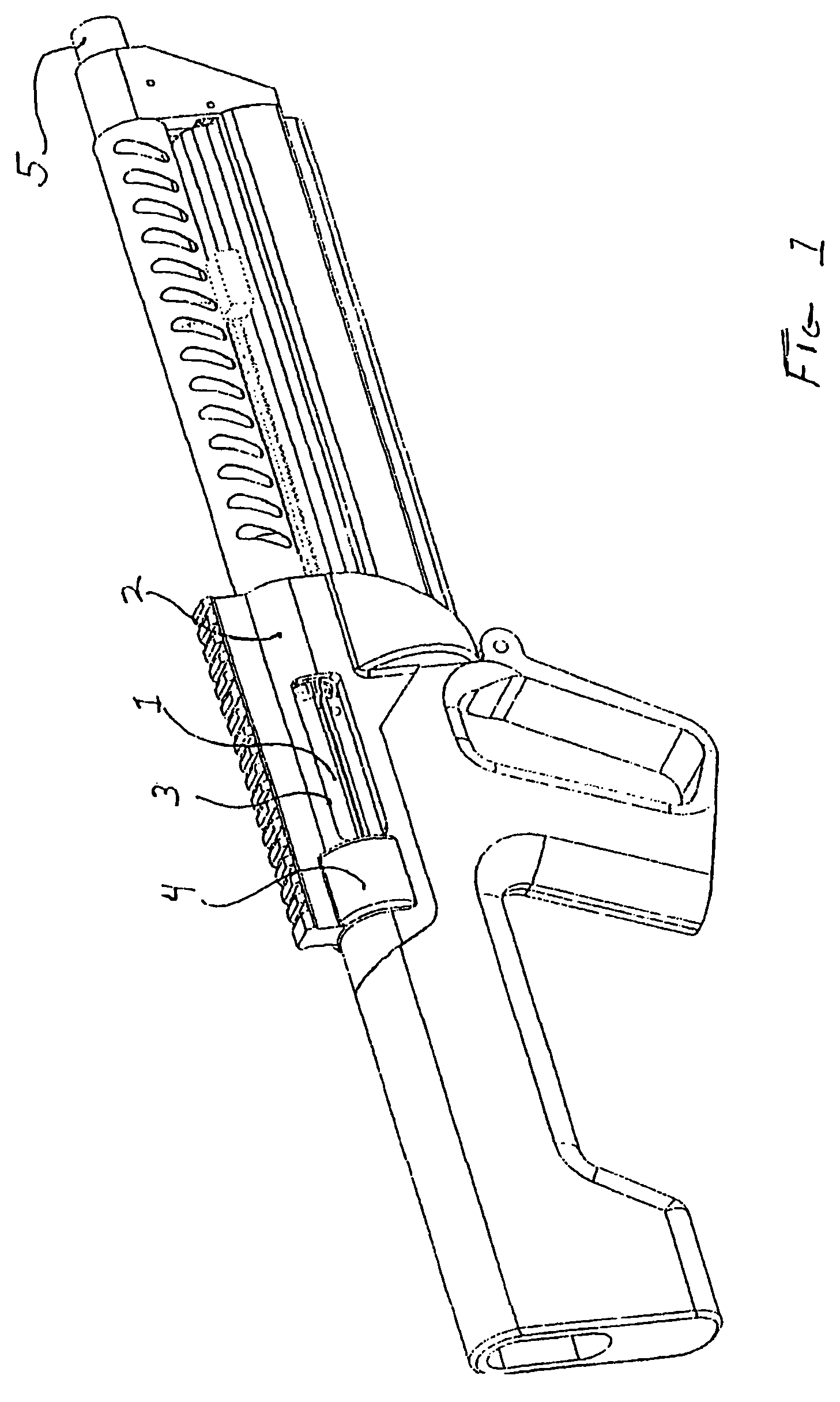
[0028]FIG. 1 depicts a semi-automatic shotgun having a roller-lock mechanism deployed within a reinforcing boss 4 on a receiver 2. A bolt 1 rides within the receiver 2 to close a firing chamber 20 in a barrel 5. The bolt 1 extends rearward past an ejection port 3 when out of battery position. It should be noted that in this and other figures, certain details of the firearm not related to the patentable aspects of the present invention—such as the trigger mechanism and magazine—are not enumerated.

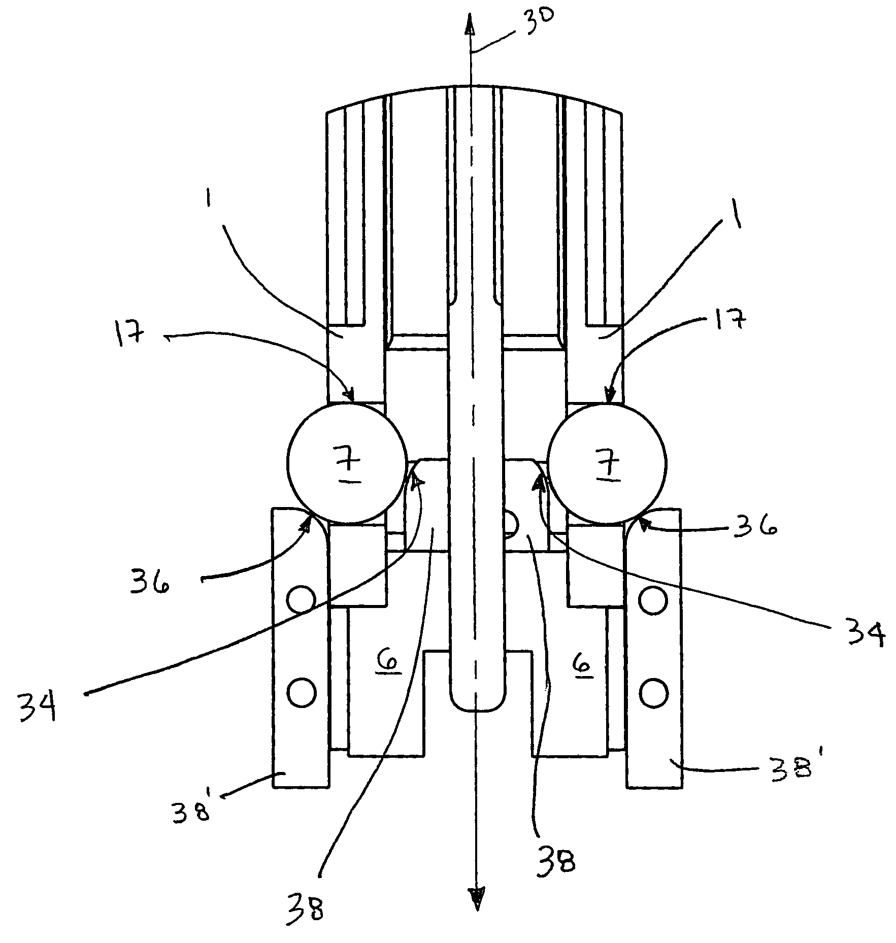
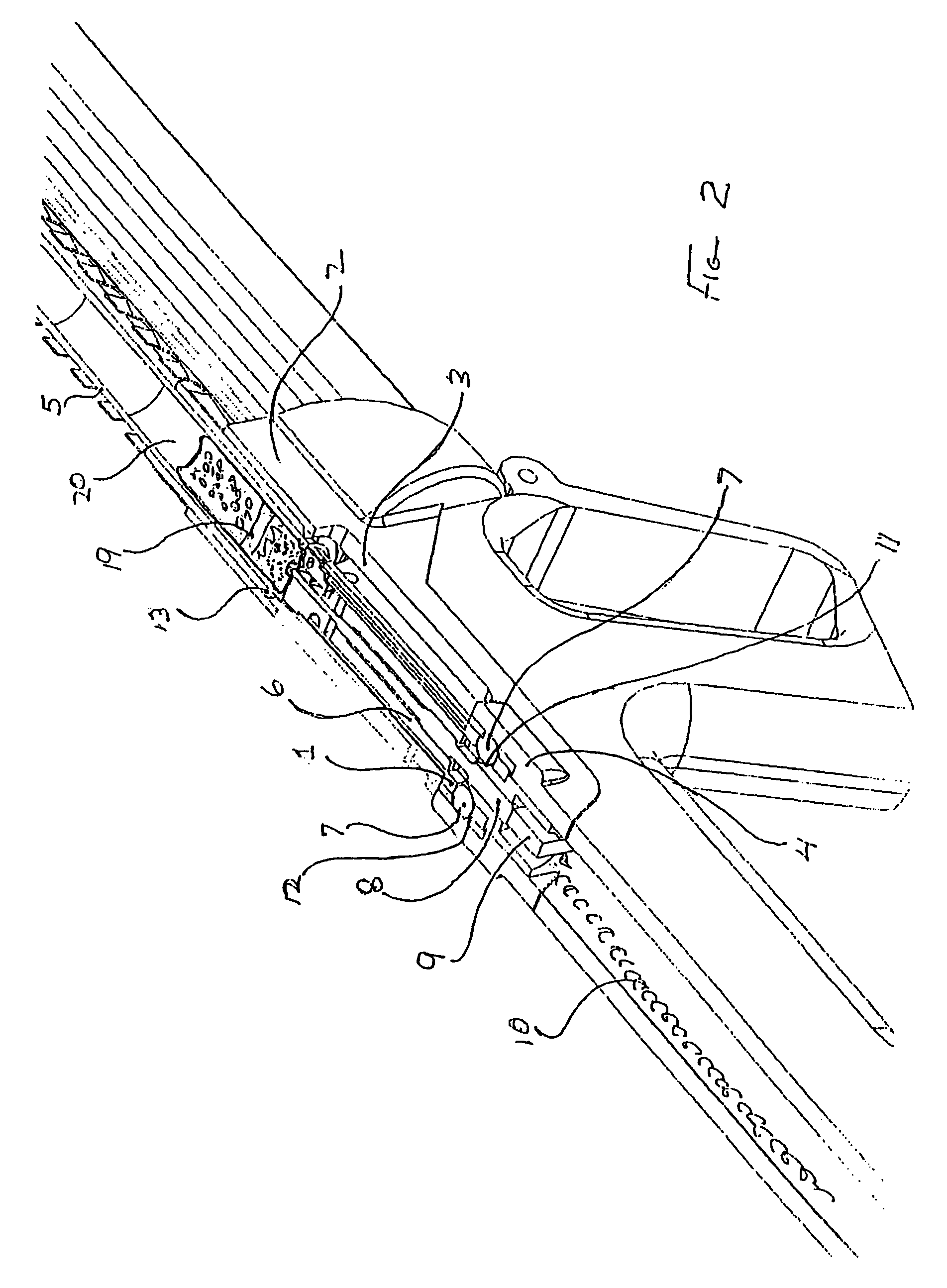
[0029]FIGS. 2 and 6 depict a partial horizontal cross-sectional view about th...


PUM


Abstract

A method and apparatus providing an action system for a semi-automatic shotgun including a receiver having an ejection port for expelling an empty cartridge of a fired projectile. The action system includes a bolt attached to a bolt carrier, wherein the bolt and the bolt carrier are movable within the receiver and substantially parallel to a longitudinal axis. A surface is attached to at least the bolt carrier or the receiver, and a roller is positioned rearward of the ejection port and proximate the surface, wherein a resistance is provided to rearward movement of at least the bolt or bolt carrier.

Description

RELATED APPLICATIONS[0001]This application is a continuation-in-part that claims the benefit of U.S. patent application Ser. No. 11 / 003,073, filed Dec. 3, 2004, now U.S. Pat. No. 7,299,737; which claims the benefit of U.S. Provisional Patent App. No. 60 / 526,540, filed Dec. 3, 2003; the contents of which are expressly incorporated herein by reference.TECHNICAL FIELD[0002]The invention relates generally to the field of firearms, and more specifically to the operating system of a firearm.BACKGROUND OF THE INVENTION[0003]The roller-lock delayed blowback action system has been employed in rifles and sub-machine guns since the 1950's and is well known to those familiar with firearm design, but it has not previously been employed in a semi-automatic shotgun. This is likely because the large diameter of the cartridge would require a disproportionately bulky mechanism and would interfere with the space necessary for feeding and ejecting the cartridges when situated near the front of the bolt...

Claims


Application Information

Patent Timeline
Patent Type & Authority Patents(United States)
IPC IPC(8): F41A3/44
CPCF41A3/46
Inventor HAJJAR, JEFFREYSTOCKTON, WARREN
Owner SNAKE RIVER MACHINE
Why Eureka
Try Eureka