Door panel integrated door stopper with operating mechanism integrated into the door lock housing

a technology of operating mechanism and door lock, which is applied in the direction of latching locks, carpet fasteners, dwelling equipment, etc., can solve the problems of not really locking the door in a position, glass in the door to break or damage to furniture or walls, and unattractive and cumbersome devices

Inactive Publication Date: 2010-09-07
SCHUMM HERMANN
View PDF8 Cites 25 Cited by
  • Summary
  • Abstract
  • Description
  • Claims
  • Application Information

AI Technical Summary

Benefits of technology

[0012]The door stopper is integrated into the door panel in the rabbet area so that it and the whole operating mechanism thereof is invisible from either side of the door panel and therefore does not detrimentally affect the appearance of the door. The door stopper according to the invention permits retaining of a door in a partially open position independently of any unevenness of the underlying floor in the pivot range of the door.
[0013]Since in the door stopper arrangement according to the invention, the operating mechanism is integrated into the door lock housing in such a way that no part projects sidewardly from the door lock housing, the door lock housing can be tightly accommodated and engaged in a slot cut into the door with a width adapted to the width of the door lock housing so that, on one hand, the door panel is not unnecessarily weakened and, on the other hand, the lock housing is firmly engaged in the door panel. And since the operating mechanism for the door stopper is coupled to the connecting members of the operating mechanism and the door stopper bolt in the rear of the lock housing, the slot in the door panel receiving the door operating mechanism housing only needs to be cut somewhat deeper, which however does not affect the tight fit of the lock housing in the door panel.
[0014]It is noted that the door stopper according to the invention cannot only be used for holding a door in a particular position, but also as a security lock for securely locking a door in a closed position. Furthermore, a locking structure may also be provided at the top of the door for additionally locking the door to the door frame at the top of the door in order to make the door even more break-in resistant.

Problems solved by technology

Those door stoppers are generally very sturdy and therefore quite voluminous so that they detract from the appearance of a door.
However, there is a need for door stoppers for doors in residential homes because it is often desirable to hold the doors partially or fully open for example for airing the rooms in a way which ensures that the door is not rapidly opened or closed by wind or drafts in such a way that damages occur by the door or door handle hitting for example furniture pieces or the wall causing possible glass in the door to break or the furniture to or walls to be damaged.
Because of the unattractive appearance of the door stoppers in connection with interior doors, there is no demand for such door stoppers and they are therefore also not available for use in connection with interior doors, and consequently other unattractive and cumbersome devices such as wedges or cords or chains are used to hold the doors in open or partially open positions.
These devices however generally do not really lock the door in a position but only prevent the door from closing, that is, they do not permit locking a door in a partially open position.
However, this known proposed structure is not usable in practice for several reasons: For one, already the arrangement of the linkage and the lever connected to the square shaft on the outside of the door lock housing is not practical since then a free space must remain next to the door lock housing in the door panel so that the lock housing is not firmly engaged within the door panel as it is the case in the normal arrangement in which the lock housing is inserted into an opening cut into the door panel so as to tightly accommodate the lock housing.
On the other hand, the arrangement is highly annoying as the door can be moved only when the door handle is pressed down which is awkward and unusual and therefore not acceptable.
The arrangement however is such that already a slight unintentional lifting of the door handle causes the release of the door stopper resulting in an unwanted blocking of the door.
The main problem however is the arrangement of the operating mechanism at both sides of the lock housing which requires space that is not available in a standard door so that a thicker door panel is needed.
In addition, the free space needed at opposite sides of the lock housing in its accommodation opening in the door panel or the door rabbet for receiving the door stop mechanism results in an unstable engagement of the lock housing in the door panel.
Further, in an arrangement known from DE 1 968 078, a door stopper, which is pre-tensioned by a compression spring in a release direction, can be pressed downwardly by way of a cam lever by upward movement of the door lever, which however does not appear to be a solution which is compatible with the common door locks.
All these arrangements do not fulfill the requirements of a normal door lock housing which has a standard size so that it can be accommodated in a standard opening for firm engagement therein.
They require additional cut outs in the door for which special tools and time are needed and which weaken the support and engagement of the door lock housing in the door.
It is therefore not surprising that those arrangements have not found acceptance in praxis.

Method used


Image

  • Door panel integrated door stopper with operating mechanism integrated into the door lock housing
  • Door panel integrated door stopper with operating mechanism integrated into the door lock housing
  • Door panel integrated door stopper with operating mechanism integrated into the door lock housing

Examples


Embodiment Construction

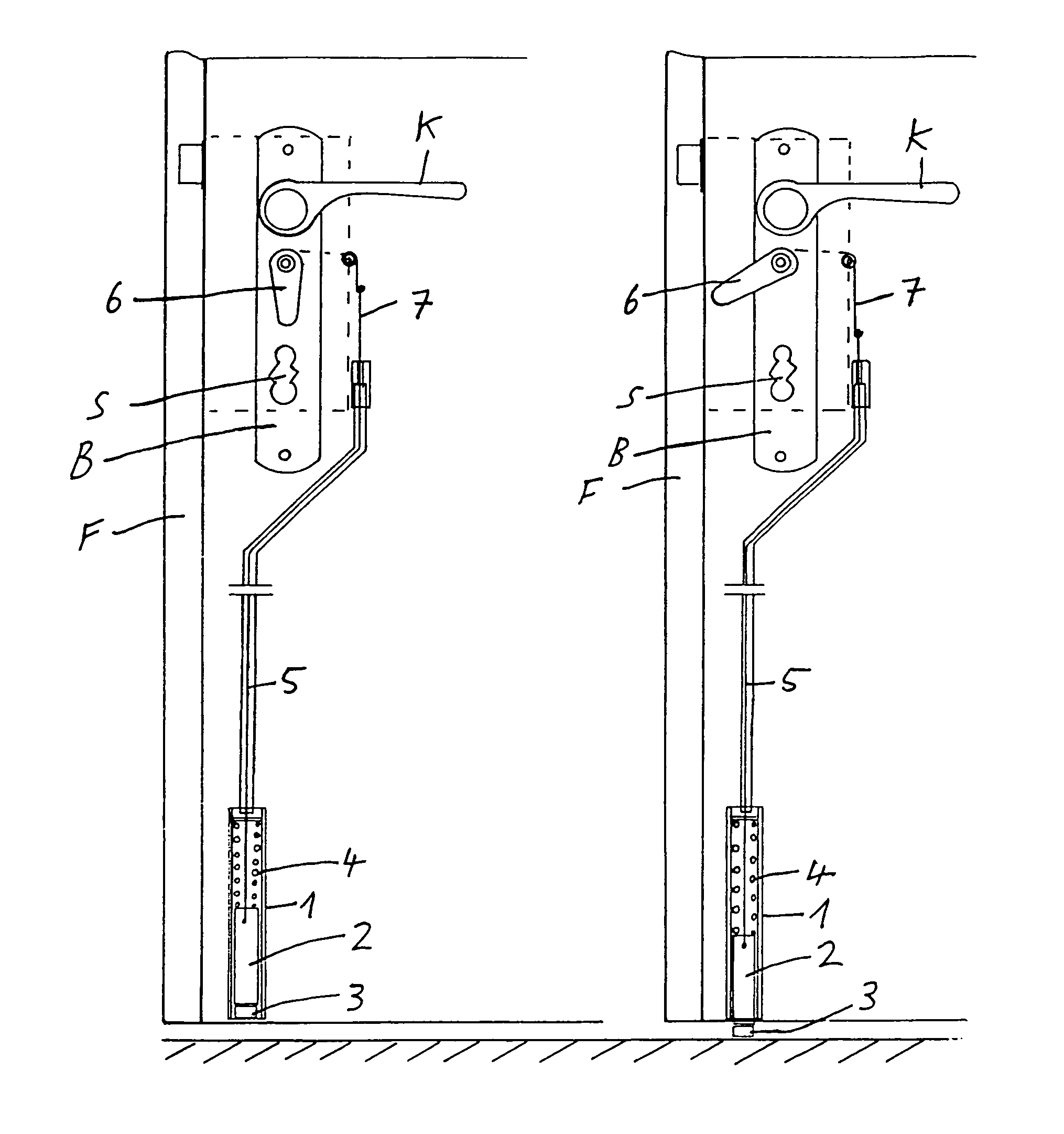
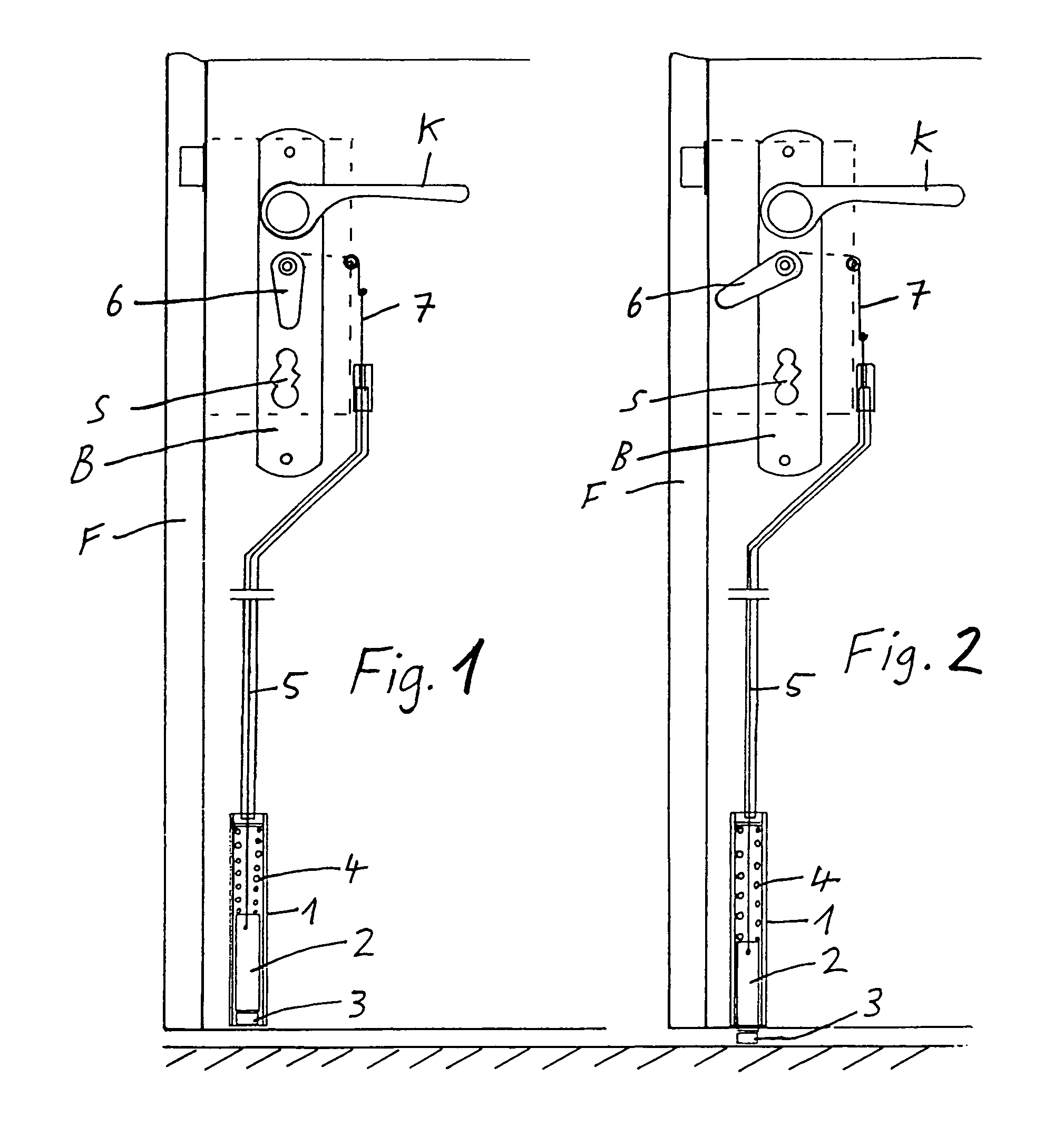
[0020]The door stopper according to the invention includes a housing 1 installed in the lower area of the door panel with a door stopper bolt 2 and a door stopper foot 3 and a compression spring 4 biasing the door stopper bolt 2 downwardly. By way of a connecting member 5, preferably in the form of a Bowden Cable, the door stopper bolt 2 is connected to an operating mechanism arranged in the lock housing of the door.

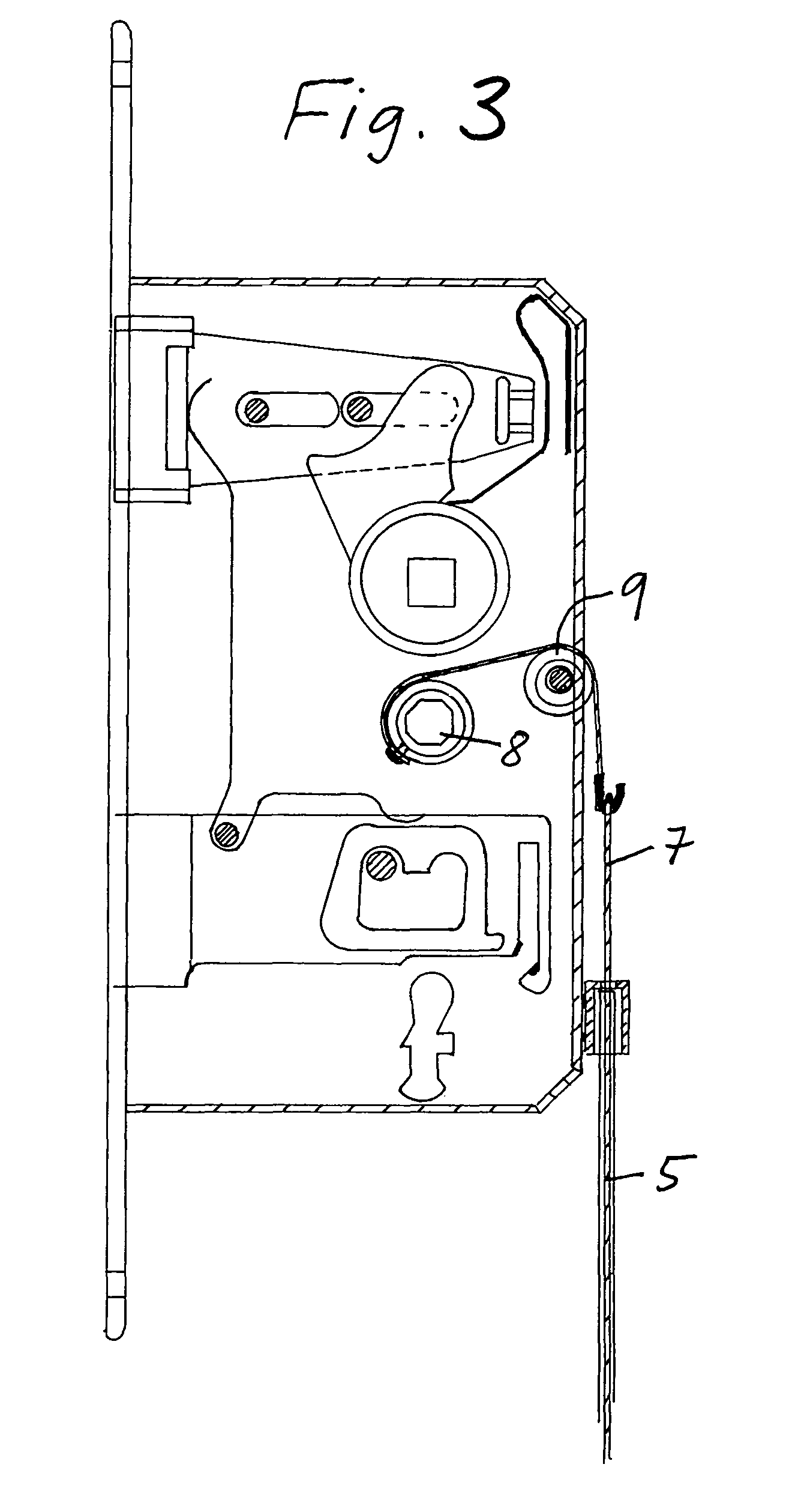
[0021]In the embodiment shown in FIGS. 1 to 5, the operating mechanism for the door stopper includes an operating lever 6 disposed at the door fitting B. FIGS. 1 and 2 show the arrangement in the door release or rest position or, respectively, in the operating position of the door stopper. FIG. 3 shows the operating mechanism for the door stopper in the door lock housing while FIG. 4 shows the door stopper mechanism operating lever 6 on the door fitting B and FIG. 5 is a plane view of the door fitting B modified to accommodate the door stopper mechanism operating lever 6...


PUM


Abstract

In a door panel integrated door stopper with a door lock housing integrated operating mechanism, comprising a door stopper bolt, a spring biasing the door stopper bolt downwardly, a pull member connected to the door stopper bolt for actuating the door stopper bolt, the operating mechanism is disposed in the door lock housing and includes an operating member movable between door stopper engagement and release positions, the operating member extends out of the lock housing through a rear wall opening thereof so that no operating structure is disposed at the side walls of the lock housing.

Description

BACKGROUND OF THE INVENTION[0001]The invention relates to a door with an integrated door stopper and an operating mechanism for the door stopper which is integrated into the door lock housing.[0002]Conventional door stoppers are usually mounted onto the door panel. They are generally designed for foot operation and generally include a bolt which is to be pushed down by a foot into engagement with an underlying floor in which position they are then locked by an engagement mechanism which can be released by a foot-actuated release lever. Those door stoppers are generally very sturdy and therefore quite voluminous so that they detract from the appearance of a door. They are therefore generally used only on house doors or other doors which need to be held open at times but not on room doors or patio or balcony doors of residential homes.[0003]However, there is a need for door stoppers for doors in residential homes because it is often desirable to hold the doors partially or fully open ...

Claims


Application Information

Patent Timeline
Patent Type & Authority Patents(United States)
IPC IPC(8): E05B59/00
CPCE05B53/005E05C17/48E05B63/08Y10S292/15Y10T70/5243Y10T70/5226Y10T292/0845
Inventor SCHUMM, HERMANN
Owner SCHUMM HERMANN
Why Eureka
Try Eureka