
Unitized appliance control panel assembly and components of the assembly

a technology of control panel and assembly, applied in the field of unitized appliance control panel assembly and components of the assembly, can solve the problems of increasing complexity and increasing the difficulty of arranging components, and achieve the effect of facilitating assembly during production and disassembly for any maintenance/repair

Active Publication Date: 2012-05-15
ELECTROLUX HOME PROD CORP NV
View PDF180 Cites 26 Cited by
  • Summary
  • Abstract
  • Description
  • Claims
  • Application Information

AI Technical Summary

Benefits of technology

The present invention provides a laundry appliance with a unitized control panel electronics. The electronics enclosure and associated components form a self-contained, unitized assembly, including control buttons and illuminated indicator elements that can be mated as a single piece with an outer user interface control panel. The front panel of the electronics enclosure provides a mounting location for various buttons and lighted indicators that will show through mating apertures provided in the control panel fascia. The invention also provides a push-button with an integrally formed planar spring mounting base, that may be backlit, such as by a PCB mounted LED. The elastic arms, which connect the button to a surrounding support, comprise linear segments extending at right angles to each other and tangentially of the button, so as to form rectangular inside corners. The button body includes a tubular portion extending rearwardly from the depressible face of the button, through the spring plane and beyond the mounting base. The invention facilitates assembly during production and disassembly for any maintenance / repair.

Problems solved by technology

As more functionality is packed into a control panel, it becomes a greater and greater challenge to arrange the components for ease of use, e.g., for function and options selection.
At the same time, the added complexity presents additional challenges from a manufacturing / assembly standpoint.

Method used


Image

  • Unitized appliance control panel assembly and components of the assembly
  • Unitized appliance control panel assembly and components of the assembly
  • Unitized appliance control panel assembly and components of the assembly

Examples


Embodiment Construction

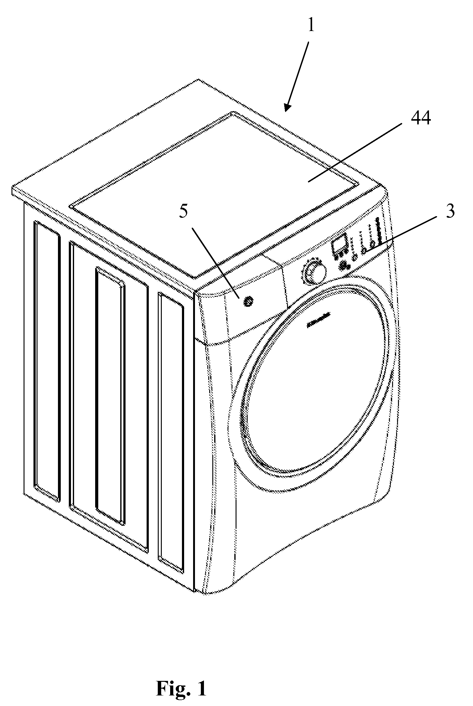
[0037]Referring to FIG. 1, illustrated is an exemplary laundry washing appliance (machine) 1 of the front-load, rotating drum variety. The washing machine includes a control panel 3 and an assembly of a drawer 5 and a housing cavity that receives the drawer alongside control panel 3 of the appliance. The drawer is extensible out of the housing to permit a user access to additive retention compartments of the drawer.

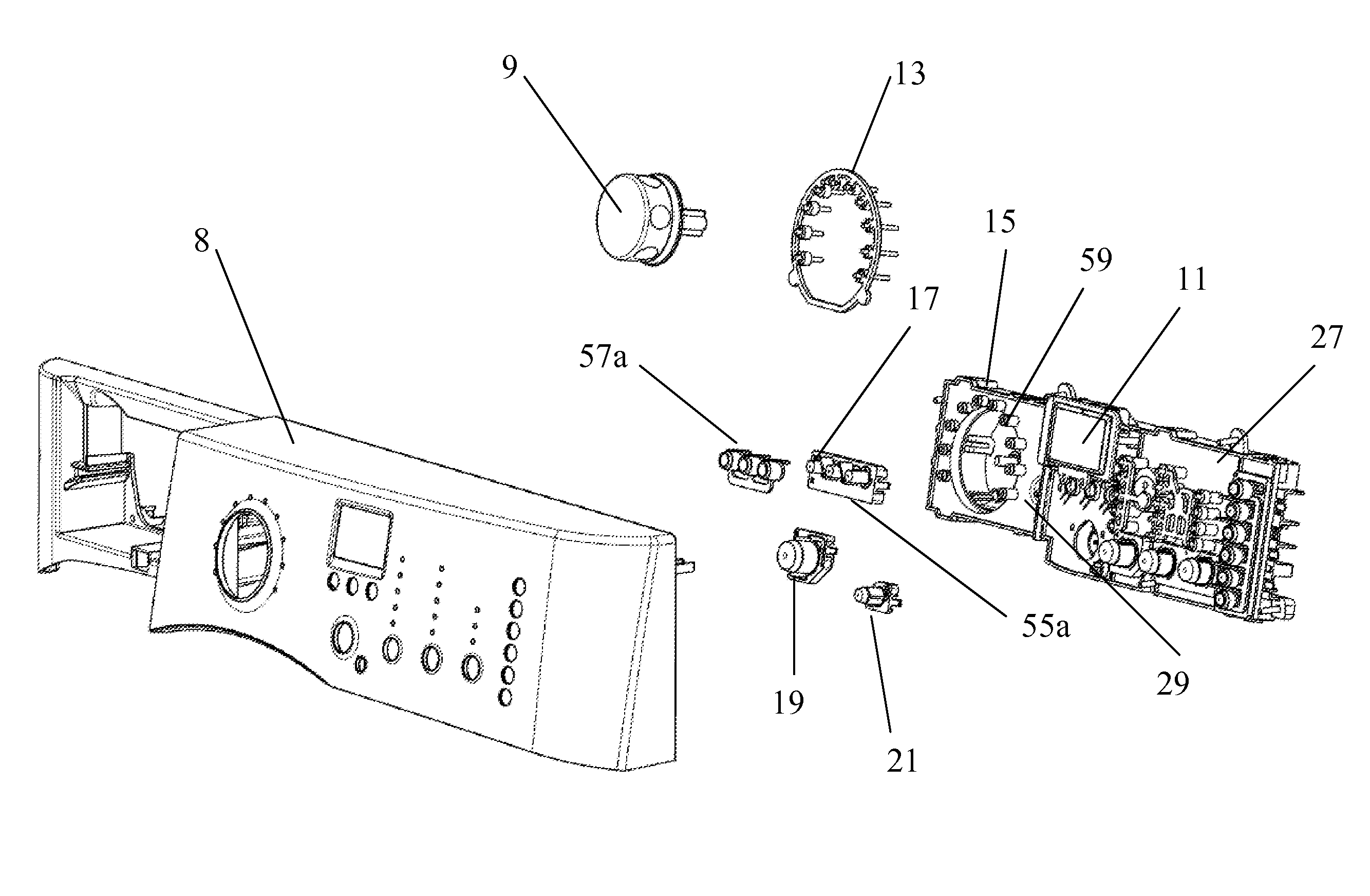
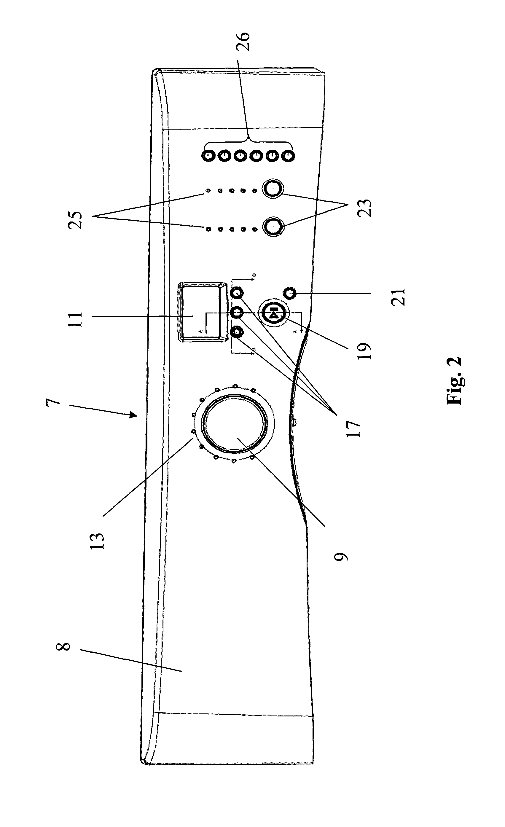
[0038]Referring now to FIG. 2, an exemplary control panel assembly 7 in accordance with the invention is shown. The control panel assembly includes a front fascia 8, which spans the width of the appliance. Received within, or in registry with, various apertures formed in the fascia 8 are a main control knob 9, an LCD display screen 11, and a plurality of operation push-buttons and illumination elements. The embodiment illustrated in FIG. 2 is generally like that seen in FIG. 1; a cavity for reception of an additives drawer is omitted, making it suitable for use in a front...


PUM


Abstract

An electronics enclosure and associated components form a self-contained, unitized assembly including control buttons and illuminated indicator elements, that can be mated as a single piece with an outer user interface control panel fascia. A front panel of the electronics enclosure provides a mounting location for various buttons and lighted indicators that will show through mating apertures provided in the control panel fascia. This may include light pipe collars and integral spring levers. Specially configured cup structures may be integrally molded at the ends of the spring levers to provide electrostatic discharge (ESD) protection. A mount of planar spring button pieces on the front enclosure panel, over the associated spring levers, results in an assembly incorporating two springs serving to bias the associated button to its return position, and eliminating any rattle or looseness of the parts.

Description

BACKGROUND OF THE INVENTION[0001]The present invention relates to appliance control panel constructions, and particularly to constructions of control panels, switches and electronics assemblies and housings suitable for use in laundry appliances, such as automated laundry washing machines and dryers.[0002]Automated laundry appliances (such as laundry washing machines and dryers) typically include an external generally rectangular cabinet, a control panel for controlling the washer / dryer operation, and a hinged lid or door that may be swung open to provide top or front-load access to a rotatable cylindrical wash basin (in the case of a washer). In use of an automated laundry washing machine, after placing a load of laundry in the wash basin, along with a suitable type and quantity of laundry detergent, a wash process is initiated by an operator through interaction with the control panel. Similarly, with a dryer, a wash load drying process is initiated through interaction with a contr...

Claims


Application Information

Patent Timeline
Patent Type & Authority Patents(United States)
IPC IPC(8): H01H9/00D06F34/30D06F34/34
CPCD06F39/005H01H2223/01H01H2231/012D06F34/34D06F2105/58D06F2105/60D06F34/30D06F2101/14
Inventor ROOSE, LEE A.MONSON, WILLIAM M.RICKLEFS, MICHAEL P.JOERGER, STEVEN J.RIPLEY, BRIAN D.MYERS, SEAN F.
Owner ELECTROLUX HOME PROD CORP NV
Learn More