Diagnostic program, a switching program, a testing apparatus, and a diagnostic method

a technology of diagnostic program and testing apparatus, applied in the direction of instruments, error detection/correction, computing, etc., can solve the problem of not being able to properly diagnose the test modul

Inactive Publication Date: 2010-09-21
ADVANTEST CORP
View PDF51 Cites 9 Cited by
  • Summary
  • Abstract
  • Description
  • Claims
  • Application Information

AI Technical Summary

Benefits of technology

[0007]Conventionally, a method for executing a diagnostic program on a control apparatus of a testing apparatus and diagnosing each part of the testing apparatus has been used with the object of detecting a fault of the testing apparatus. Here, the kind of a test module inserted into each slot of the conventional testing apparatus is predetermined. Thus, conventionally, an object diagnostic program for diagnosing a test module which is an object to be diagnosed inputs and outputs a signal for diagnosis between the test module to be diagnosed and a known test module. In other words, the object diagnostic program performs input and output of a signal for diagnosis between the test module to be tested and another test module of a predetermined kind by calling a signal for diagnosis input and output program for controlling another test module.

Problems solved by technology

In case this kind of testing apparatus is programmed so as to call a signal for diagnosis input and output program for controlling another test module of a predetermined kind from an object diagnostic program of a test module which is an object to be tested similarly with the conventional testing apparatus, it is impossible to properly diagnose the test module if another test module provided in the testing apparatus is changed.

Method used


Image

  • Diagnostic program, a switching program, a testing apparatus, and a diagnostic method
  • Diagnostic program, a switching program, a testing apparatus, and a diagnostic method
  • Diagnostic program, a switching program, a testing apparatus, and a diagnostic method

Examples


Embodiment Construction

[0026]The invention will now be described based on the preferred embodiments, which do not intend to limit the scope of the present invention, but exemplify the invention. All of the features and the combinations thereof described in the embodiment are not necessarily essential to the invention.

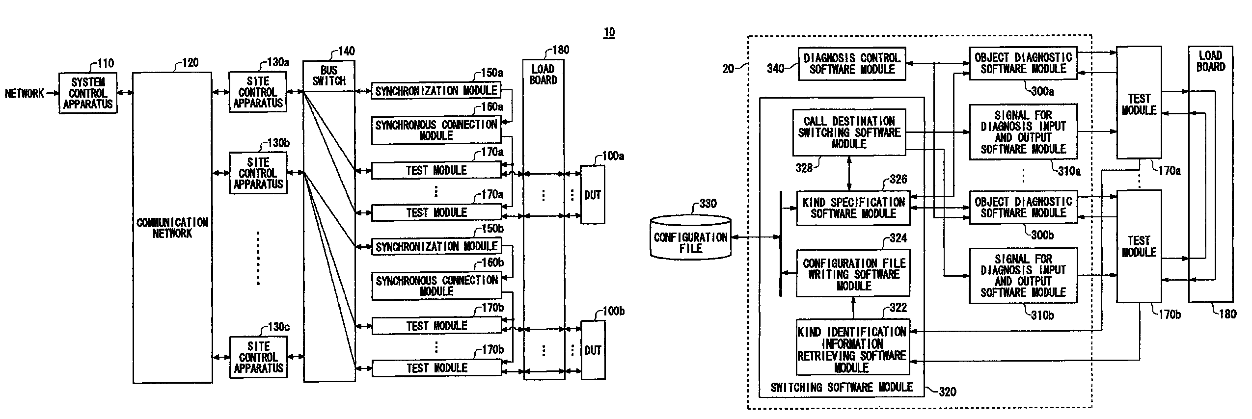
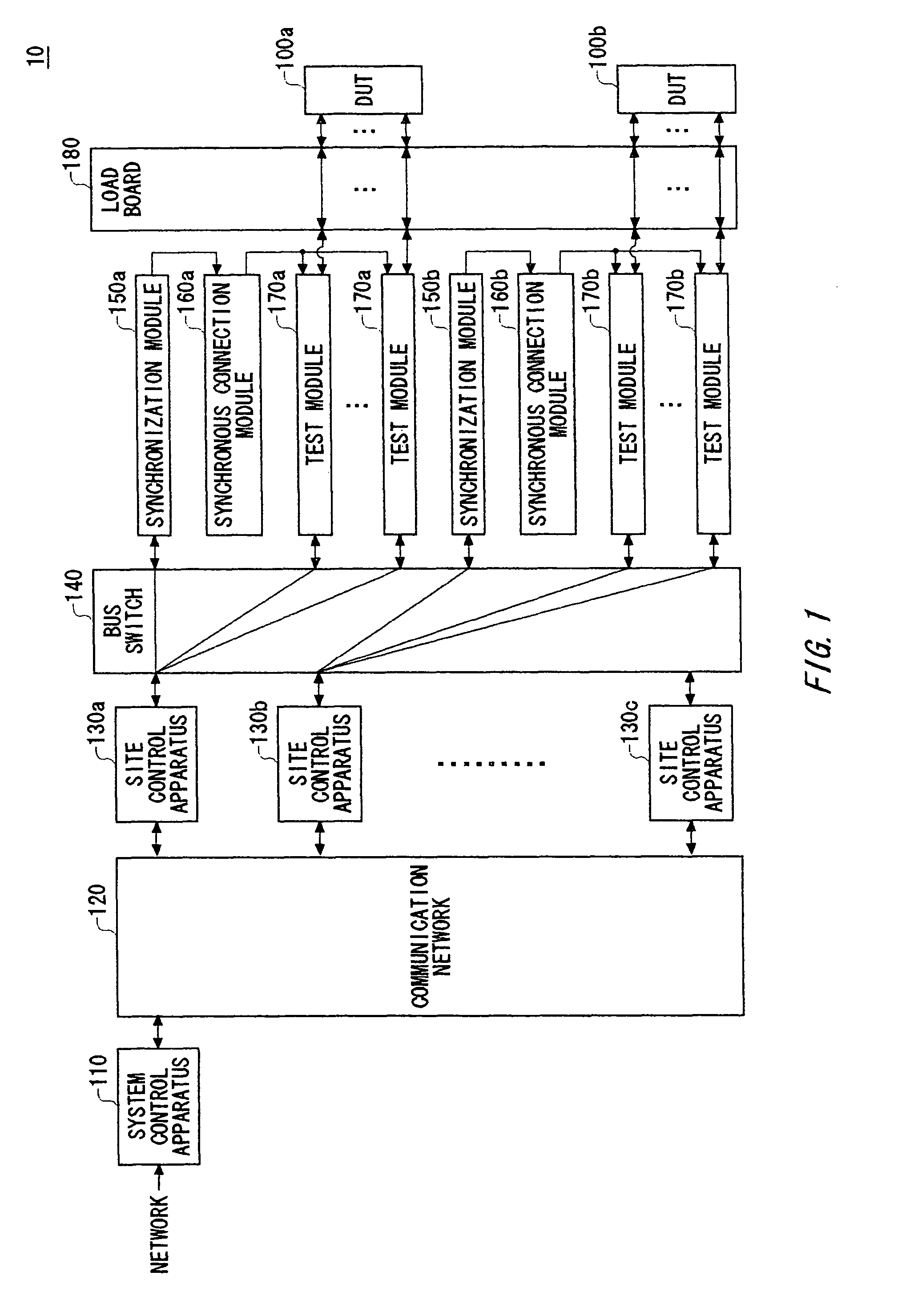
[0027]FIG. 1 shows the configuration of a testing apparatus 10 according to an embodiment of the present invention. The testing apparatus 10 generates a test signal and provides with a Device Under Test (“DUT”) 100 with it. The testing apparatus 10 determines pass / fail of the DUT 100 on the basis of whether or not an output signal, which the DUT 100 outputs as a result of operating according to the test signal, coincides with an expectation value. The testing apparatus 10 according to the present embodiment is realized by an open architecture and may use various modules based on the open architecture as a test module 170 for providing the DUT with the test signal and the like.

[0028]The testin...


PUM


Abstract

A diagnostic program includes a first software module that diagnoses a diagnostic object test module; a plurality of second software modules respectively corresponding to the type of the non-diagnostic object test module, and controlling the non-diagnostic object test module to receive a signal for diagnosis output by the diagnostic object test module or to output a signal for diagnosis to the diagnostic object test module; a third software module specifying the second software module that corresponds to the type of the non-diagnostic object test module, in response to a call received from said first software module which instructs said third software module to receive the signal for diagnosis from or send the signal for diagnosis to the non-diagnostic object test module; and a fourth software module which calls the second software module specified by said third software module, and causes the signal for diagnosis to be input or output.

Description

CROSS REFERENCE TO THE RELATED APPLICATION[0001]This patent application claims priority from a Japanese patent application No. 2005-100018 filed on Mar. 30, 2005, the contents of which are incorporated herein by reference.BACKGROUND OF THE INVENTION[0002]1. Field of the Invention[0003]The present invention relates to a diagnostic program, a switching program, a testing apparatus, and a diagnostic method. More particularly, the present invention relates to a diagnostic program, a switching program, a testing apparatus, and a diagnostic method for diagnosing a test module and the testing apparatus includes a plurality of test modules for providing a device under test with a test signal and a control apparatus for controlling the plurality of test modules.[0004]2. Description of the Related Art[0005]A testing apparatus for testing a device under test (“DUT”) such as a memory, a logic LSI, or a Soc (System on Chip) determines pass / fail of the DUT, for example, by providing a test signal...

Claims


Application Information

Patent Timeline
Patent Type & Authority Patents(United States)
IPC IPC(8): G06F11/00
CPCG01R31/31901G01R31/28G01R35/00G06F11/00
Inventor IWAMOTO, SATOSHI
Owner ADVANTEST CORP
Why Eureka
Try Eureka