Fault detection circuit for a driver circuit

a driver circuit and fault detection technology, applied in the direction of power supply testing, dynamo-electric converter control, pulse technique, etc., can solve the problems of motor not being controlled, circuit failure to detect, motor may behave in an unpredicted manner,

Active Publication Date: 2005-10-06
HONDA MOTOR CO LTD
View PDF7 Cites 11 Cited by
  • Summary
  • Abstract
  • Description
  • Claims
  • Application Information

AI Technical Summary

Benefits of technology

[0010] Thus, according to the present invention, by applying a test voltage of a limited current capacity to a suitable test point of the driver circuit before the power up of the drive circuit, any fault in the drive source or other components of the driver circuit can be detected before the power up of the driver circuit so that a suitable countermeasure may be taken. The test current is so small that the drive sources would not be inadvertently activated and various components would not be damaged even when there is any faulty component in the driver circuit. When any faulty component is detected in the testing process, the driver circuit may be prevented from being powered up or a warning is made so that any undesired operation of the drive sources or permanent damage to various components owing to such a faulty component may be avoided.

Problems solved by technology

However, according to such monitoring and detecting circuits, a failure of the circuit can be detected only after the electric current is supplied to the motor.
Therefore, when the electric motor is applied to an automotive closure such as a power slide door, power window or sunroof, the user may discover that the motor cannot be controlled after turning on the electric motor, and the motor may behave in an unpredicted manner.
Also, the failure in the motor driver circuit may be discovered only after the vehicle has started running.
It is possible to install a fail-safe circuit to totally disable the motor when a failure of the driver circuit is detected, but it requires additionally circuit elements and undesirably increases the complexity of the driver circuit.
Even when an abnormal motor current is detected, it was not possible to determine if the failure is in the electric motor or in the driver circuit.
Therefore, the countermeasure that may be taken may not be proper if the cause of the failure cannot be determined.
For instance, when there is any short-circuiting in the driver circuit, excessive motor current may be supplied to the motor, thereby damaging the electric motor or other circuit elements.
When the failure is caused by a circuit element, the motor cannot be controlled as desired.

Method used


Image

  • Fault detection circuit for a driver circuit
  • Fault detection circuit for a driver circuit
  • Fault detection circuit for a driver circuit

Examples


Embodiment Construction

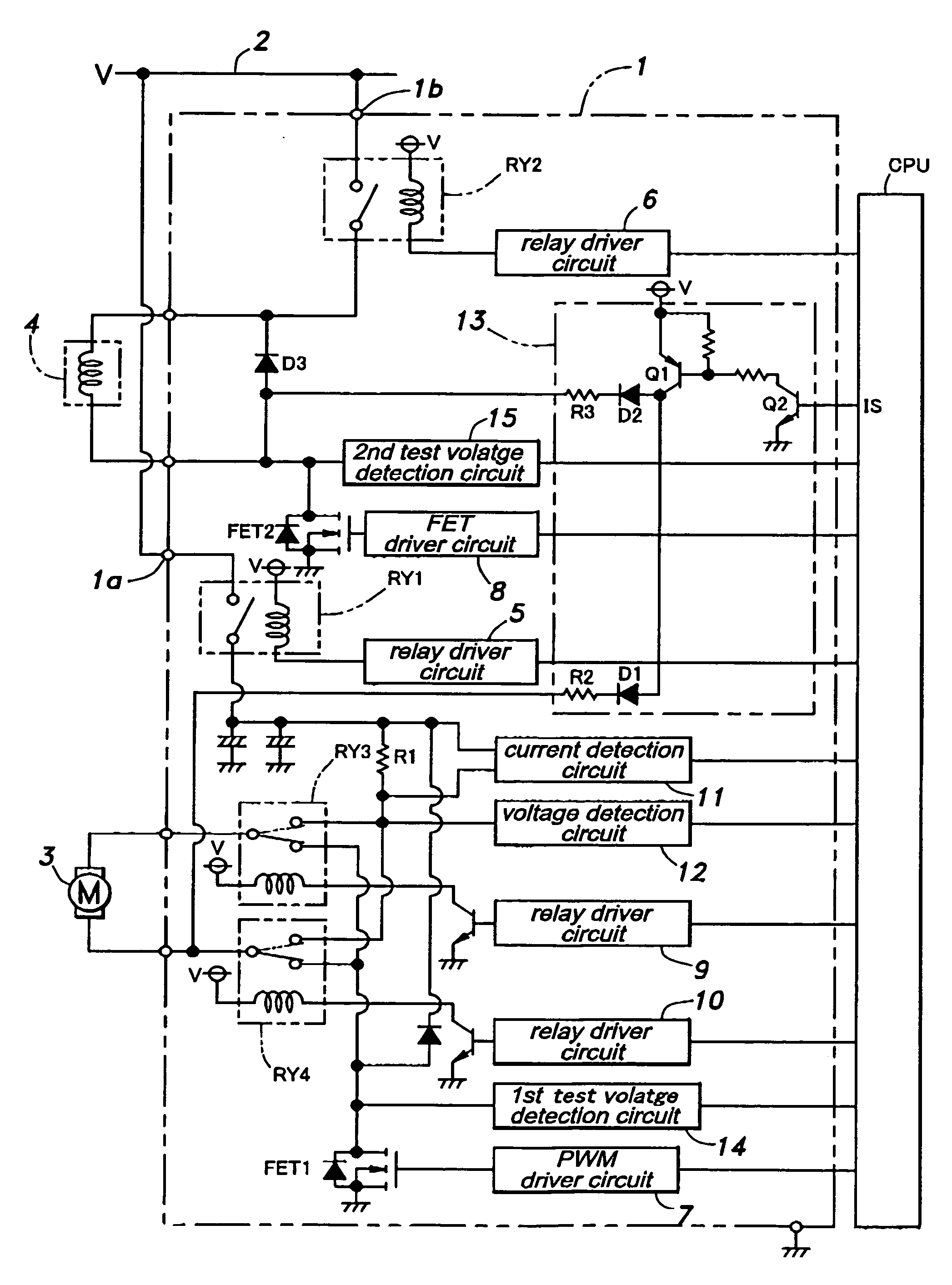
[0016]FIG. 1 shows a simplified circuit diagram of a driver circuit embodying the present invention. This driver circuit can be used, for instance, in controlling an automotive closure system such as a power slide door, a power window, a sunroof or the like. As shown in the drawing, power terminals 1a and 1b of the driver circuit 1 are connected to a positive power line 2 of a battery (V=12 volts, for instance) not shown in the drawing. The output end of the driver circuit 2 is connected to drive sources such as an electric motor 3 and a magnetic clutch 4 that are used for controlling the movement of an automotive slide door not shown in the drawings. The clutch 4 is engaged when the slide door is to be actuated by the electric motor 3. When the clutch 4 is disengaged, the slide door may be moved freely by hand. The clutch 4 is provided with a solenoid not shown in the drawings that engages the clutch when energized and disengages the clutch when de-energized.

[0017] One of the powe...


PUM


Abstract

Various component parts of a driver circuit for drive sources such as electric motors and clutches, such as relays and FETs as well as the drive sources can be tested by selectively energizing the relays and evaluating the voltage levels of the selected points by using the first and second test voltage detection circuits. This testing process is typically executed before the power up of the drive circuit. The test current is so small that the drive sources would not be inadvertently activated and various components would not be damaged even when there is any faulty component in the driver circuit. When any faulty component is detected in the testing process, the driver circuit may be prevented from being powered up so that any undesired operation of the drive sources or permanent damage to various components owing to such a faulty component may be avoided.

Description

TECHNICAL FIELD [0001] The present invention relates to a fault detection circuit for detecting a normal / abnormal state of a driver circuit for driving a drive source such as electric motors, clutches and solenoids. BACKGROUND OF THE INVENTION [0002] Conventionally, in a reversible driver circuit for driving an electric motor, a bridge circuit including a relay in each arm of the bridge circuit was typically used. It was customary to connect a shunt resistor in the ground end of the electric motor for detecting the motor current, and monitor the state of the driver circuit by comparing the detected motor current with the pulse signal that controls the operation of the motor. Such an arrangement is disclosed, for instance, in Japanese patent laid open publication No. 07-213092 (in particular, pages 3-4 and FIG. 2). [0003] It is also known to connect an FET between a power source and a switch for reversing the polarity of the current supplied to the motor, and to prevent the applicati...

Claims


Application Information

Patent Timeline
Patent Type & Authority Applications(United States)
IPC IPC(8): G01R31/08G01R31/40H02K17/32H02K23/68H02K27/30H02P7/00
CPCG01R31/40H03K17/687H03K17/18H03K17/0812
Inventor SHIMOYAMA, MIKIHITOKAWAKURA, TAKAYUKIOGAWA, TOMOYUKISHIGA, NAOHIKOYANAGITA, YUICHITANINO, KATSUHIRO
Owner HONDA MOTOR CO LTD
Why Eureka
Try Eureka