Connection to grid type engine generator apparatus

a generator and grid-type technology, applied in the direction of electrical equipment, electrical generator control, control systems, etc., can solve the problems of stalling or hunting down of revolutions, and achieve the effect of improving the accuracy of fault detection and minimizing the negative effects of system sources at the interconnection

Inactive Publication Date: 2004-06-01
HONDA MOTOR CO LTD
View PDF34 Cites 12 Cited by
  • Summary
  • Abstract
  • Description
  • Claims
  • Application Information

AI Technical Summary

Benefits of technology

A second feature of the present invention is that the output of the inverter is gradually increased at the start of the interconnection with the power system source. When the engine is interconnected with a large load such as a rated load after warming up, it may cause hunting or slowdown (stalling) of the revolution. According to the second feature, while the engine runs steadily, its adverse effects on the system source at the interconnection can be minimized. As a result, the direct current voltage which is susceptible to the exertion of large loads on the engine can be maintained stable and its change which results in misjudgment for the fault detection can be eliminated.
A third feature of the present invention is comprising a means where a generator fault signal is outputted, when the canceling and the re-start of the interconnection with the power system is repeated, the fault detecting means examines whether or not the generator has a fault. According to the third feature, the generator fault signal is outputted when frequent canceling and re-start interconnection with the power system occurred. This prudent judgment improves the accuracy of the fault detection.

Problems solved by technology

When the engine is interconnected with a large load such as a rated load after warming up, it may cause hunting or slowdown (stalling) of the revolution.

Method used


Image

  • Connection to grid type engine generator apparatus
  • Connection to grid type engine generator apparatus
  • Connection to grid type engine generator apparatus

Examples


Embodiment Construction

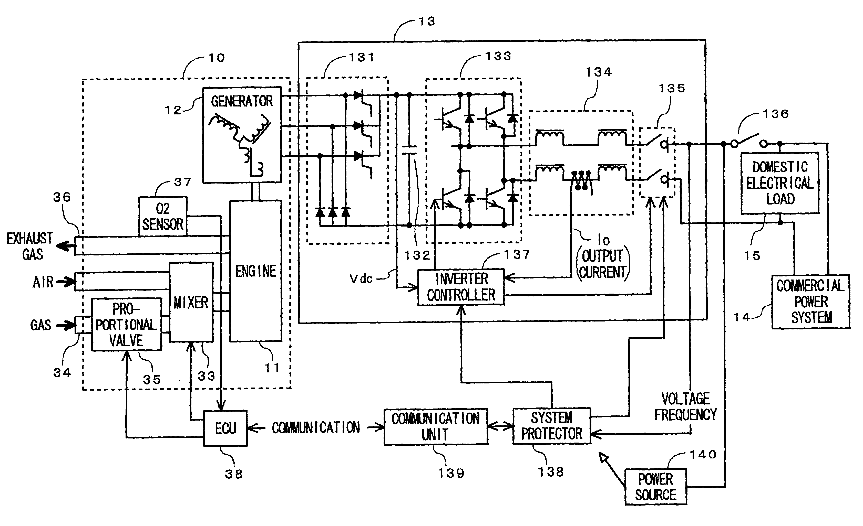
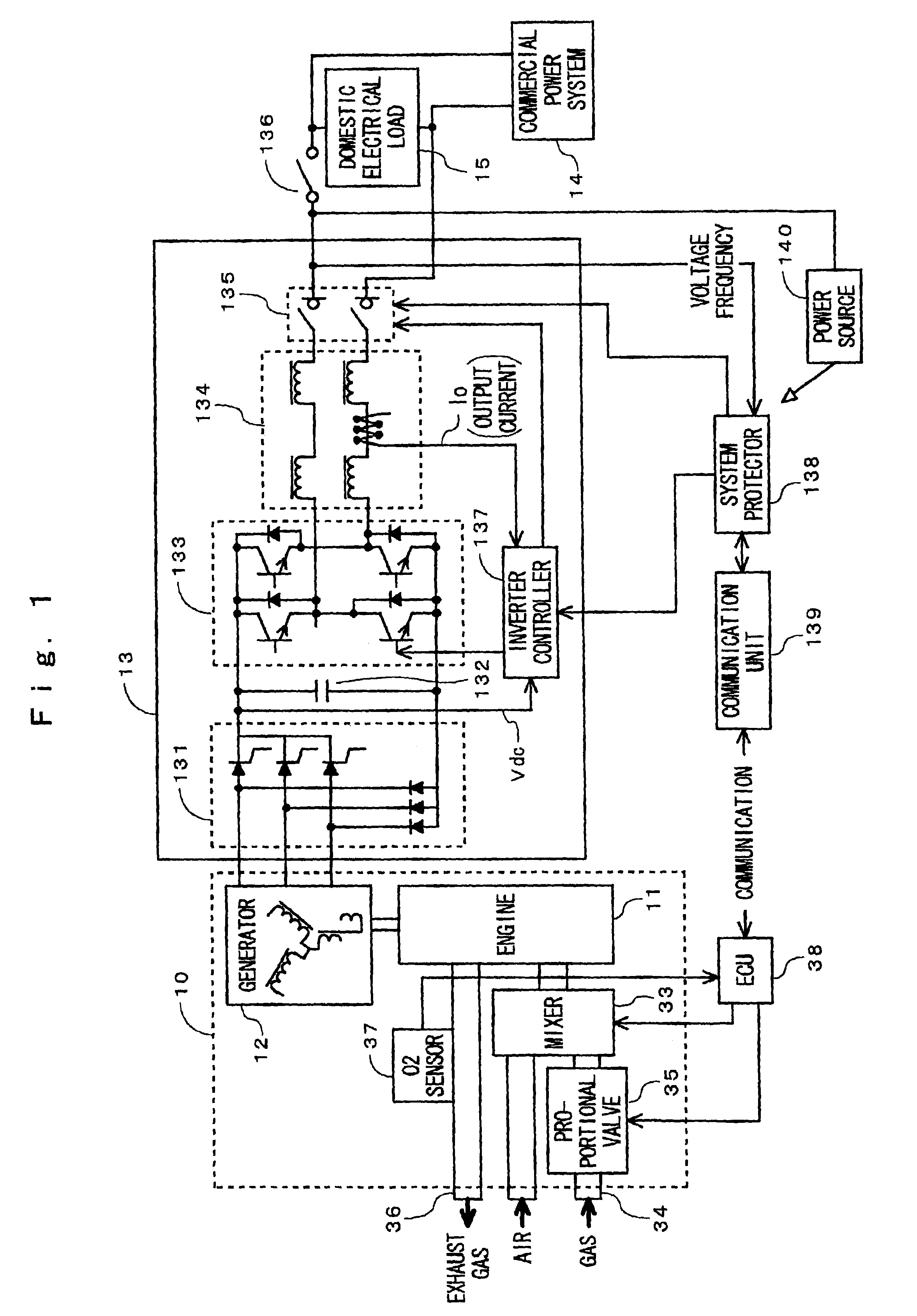
One embodiment of the present invention will be described in more detail referring to the relevant drawings. FIG. 1 is a block diagram of the engine generator apparatus. As shown, an engine operated generator 10 comprises an engine 11 and a generator 12. The generator 12 is driven by the engine 11 for generating an alternating current output responding to the number of revolutions. The generator 12 comprises a rotor joined to the engine 11 and a stator on which three phase windings are wound. The output terminal of the three phase windings is connected with an inverter unit 13. The inverter unit 13 converts the alternating current output of the generator 12 into an alternating current of the quality equivalent (in voltage, frequency, noise, and other factors) to that of the commercial power supply, then the output is connected to the commercial power system as timed in phase with the same of the system.

More specifically, the inverter unit 13 comprises a converter 131 for converting ...


PUM


Abstract

A fault on the generator can be detected with the use of a simple arrangement. The output of the generator 12 which has multi-phase winding and is driven by an engine 11 is rectified and then converted by an inverter 133 into an alternating current at the frequency of a system before interconnected to the source of the system. After the engine 11 is started, the direct current voltage Vdc is monitored with a first fault monitor 40. When the direct current voltage Vdc rises up to a predetermined level, a connector relay 135 is closed. As the output of the inverter 133 is increased, the interconnection with the system source is enabled. After the interconnection, the direct current voltage and the output of the inverter are monitored with a second fault monitor 43. If the direct current voltage drops down to below the predetermined level before the output of the inverter reaches a rated level, the canceling and re-interconnection is repeated. Then, when the direct current voltage remains below the predetermined level after the re-interconnection, it is judged that the generator 12 has a fault such as a line breakage in the windings disconnection.

Description

BACKGROUND OF THE INVENTION1. Field of the InventionThe present invention relates to an engine generator apparatus and particularly to an engine generator apparatus such as a generator facility for private use or a small-sized cogeneration system having a function for interconnecting with an electric power grid.2. Description of the Related ArtGenerator apparatuses for private use have widely been provided for emergency use in case of blackout or power failure. Recently, private use cogeneration type generator apparatuses which can be interconnected with electric power systems for improvement of the efficiency of operation are getting popular. Such a cogeneration type private use generator apparatus comprises a small generator driven by a gasoline engine or a gas engine fueled with gas fuel such as town gas.For smooth interconnection or parallel operation of a electric power grid, the cogeneration type generator apparatus needs to comply with the guideline for technical requirements...

Claims


Application Information

Patent Timeline
Patent Type & Authority Patents(United States)
IPC IPC(8): H02J3/38H02P9/00H02P9/04H02P9/08
CPCH02J3/38Y02E20/14
Inventor FUKUSHIMA, TOMOKIKOTANI, YOSHIAKITAMECHIKA, TAKAOKAMIMURA, KENJI
Owner HONDA MOTOR CO LTD
Why Eureka
Try Eureka