
Method and apparatus for minimizing adverse effects of thermal expansion in a heat exchange reactor

a technology of heat exchange reactor and thermal expansion, which is applied in the direction of lighting and heating apparatus, gas-gas reaction process, laminated elements, etc., can solve the problems of difficult provision of features in tubular array heat exchange reactors, particularly difficult thermal stresses, and thermal stresses, so as to reduce thermal stresses, increase the strength of tubes, and enhance corrosion resistance

Inactive Publication Date: 2006-10-10
LAIR LIQUIDE SA POUR LETUDE & LEXPLOITATION DES PROCEDES GEORGES CLAUDE
View PDF12 Cites 51 Cited by
  • Summary
  • Abstract
  • Description
  • Claims
  • Application Information

AI Technical Summary

Benefits of technology

This configuration reduces thermal stresses, enhances corrosion resistance, increases tube strength, and minimizes material usage, leading to a more durable and efficient heat exchange reactor with improved operational life and reduced size and weight.

Problems solved by technology

If free expansion is not allowed for in the configuration of the heat exchange reactor, then the unrealized strains result in thermal stresses.
The thermal stresses are particularly challenging in hydrocarbon steam reformers because the temperature gradients are generally very high.
The provision of features in tubular array heat exchange reactors presents formidable challenges due to the thermal gradients along the axis of the tubes.
These forces can cause premature structural failure of the reactor unless exceptionally strong tubes are employed, which is undesirable for several reasons, including an objectionable increase in the material usage in the construction of the reactor, as well as an attendant increase in volume and weight of the reactor.

Method used


Image

  • Method and apparatus for minimizing adverse effects of thermal expansion in a heat exchange reactor
  • Method and apparatus for minimizing adverse effects of thermal expansion in a heat exchange reactor
  • Method and apparatus for minimizing adverse effects of thermal expansion in a heat exchange reactor

Examples


Embodiment Construction

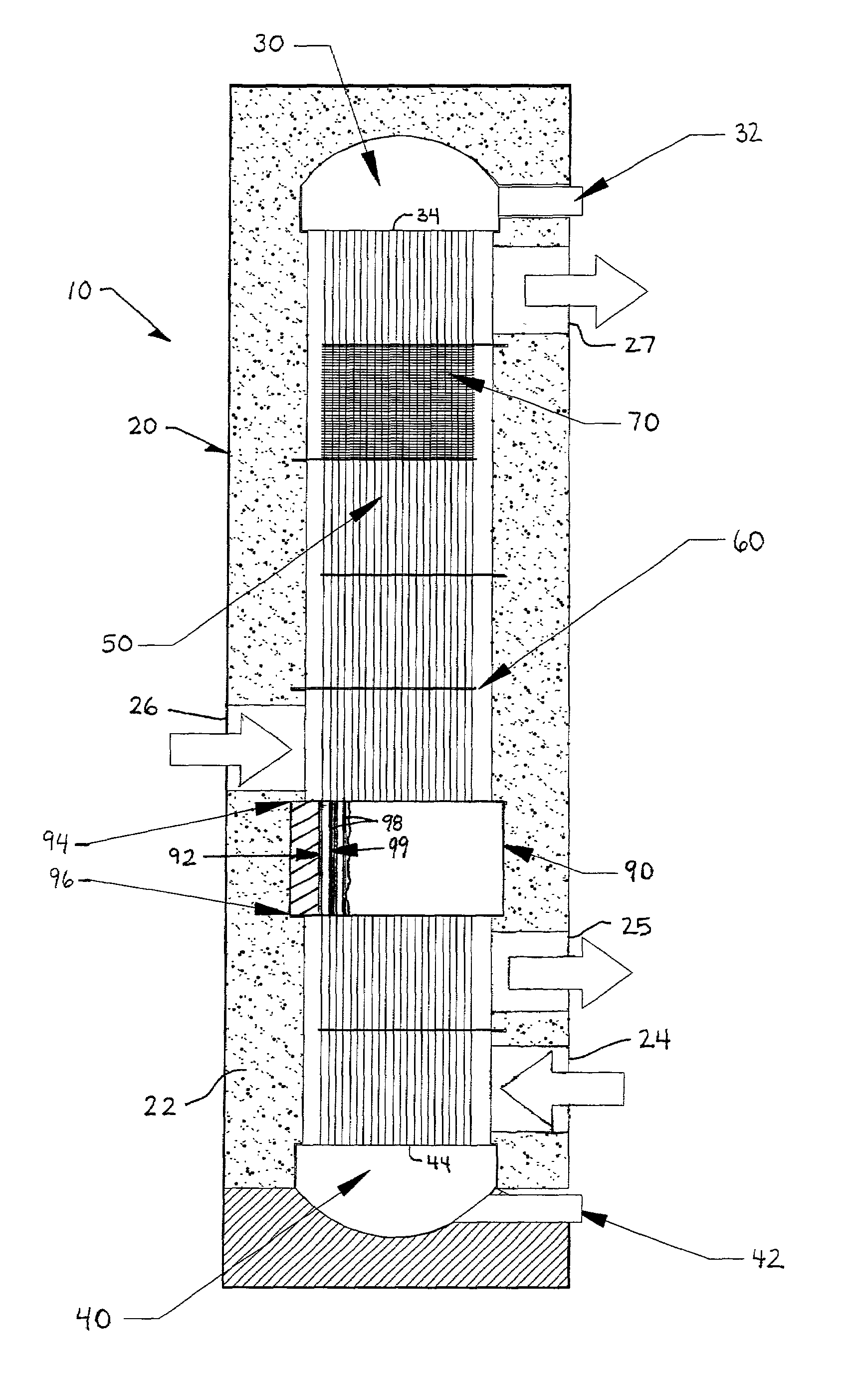
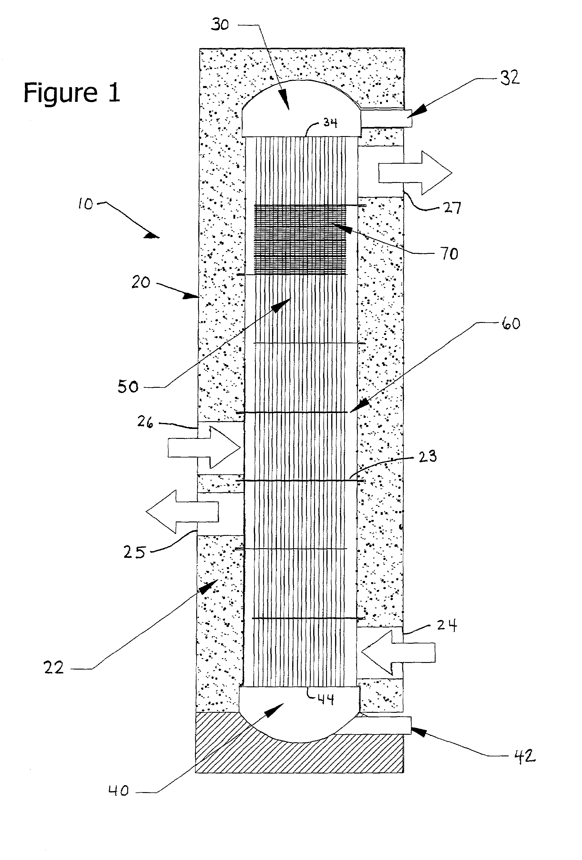
[0024]FIG. 1 depicts the core of a tubular heat exchange reactor 10. The reactor 10 includes a housing 20 that encloses a plurality of tubes 50 that are mechanically connected at one end to a header plate 34 of a first manifold assembly 30 and at an opposing end to a header plate 44 of a second manifold assembly 40. The first manifold assembly 30 is provided with a first fluid inlet port 32 and the second manifold assembly is provided with an exit port 42. The first fluid flows through inlet 32 to the first manifold assembly 30, the first manifold assembly 30 distributes through the first fluid to the plurality of tubes 50 to the second manifold assembly 40, and the first fluid then flows through exit 42. The first fluid flowing through the tubes 50 is in heat exchange contact with at least one second fluid that is provided within the housing 20 and is in contact with an outer surface 51 (labeled in FIG. 5) of the tubes 50.

[0025]The heat exchange reactor 10 includes baffles 60 loose...


PUM

PropertyMeasurementUnit
outer diametersaaaaaaaaaa
temperatureaaaaaaaaaa

Abstract

A heat exchange reactor including a housing, a plurality of tubes mounted in the housing and configured to carry a first fluid, and a baffle having a plurality of holes receiving the tubes. The baffle is configured to guide a second fluid provided within the housing to flow in a direction generally perpendicular to the tubes. The reactor includes various configurations for minimizing adverse effects of thermal expansion of the baffle and the tubes. The reactor is configured to minimize mechanical interference between the baffle and the tubes in both an operational state and a non-operational state, for example, by shaping the holes in the baffle to take into account thermal expansion. The reactor also includes a thermal insulator along a length of the tubes at a large temperature gradient zone within the reactor. The reactor further includes a heat transfer fin in contact with only one of the tubes.

Description

BACKGROUND OF THE INVENTION[0001]1. Field of the Invention[0002]The present invention relates to heat exchange reactors and methods of constructing heat exchange reactors.[0003]2. Discussion of the Background[0004]Heat exchange reactors are often employed to carry out chemical reactions where significant quantities of heat must be added or removed from a first reacting fluid to a second heat transfer fluid, which may or may not be reacting. These heat exchange reactors often bear a strong resemblance to simple heat exchangers, but are often provided with additional features such as fixed beds of catalysts, specialized flowpath designs, exotic materials and the like. Heat exchange reactors are constructed in many forms, including plate-fin and tubular arrays.[0005]An example of a reaction conducted in heat exchange reactors is the steam reformation of hydrocarbon feedstocks to produce hydrogen-containing gas mixtures. In this process, a mixture of steam and hydrocarbon is passed thro...

Claims


Application Information

Patent Timeline
Patent Type & Authority Patents(United States)
IPC IPC(8): F28F9/22F28D21/00F28F1/32B01JB01J2/00B01J8/00B01J8/06B01J12/00B01J19/00B01J19/24C01B3/34F28D7/00F28D7/10F28D7/16F28D9/00F28F1/42F28F3/00F28F7/00F28F9/013F28F9/02F28F13/14
CPCB01J8/008B01J8/067B01J19/0013B01J19/006B01J19/2425C01B3/34F28D7/0066F28D7/0091F28D7/1653F28F9/22F28F13/14B01J2208/00221B01J2208/00495B01J2219/00094B01J2219/00155B01J2219/00777C01B2203/0233C01B2203/0805F28F2265/26F28F21/083F28D7/00F28F7/00F28F9/02
Inventor LOMAX, JR., FRANKLIN D.STREEKS, MICHAEL SEANWAIDE, STEPHEN
Owner LAIR LIQUIDE SA POUR LETUDE & LEXPLOITATION DES PROCEDES GEORGES CLAUDE
Learn More