Non-contact Biometric Monitor

a biometric monitor and non-contact technology, applied in the field of monitoring systems, can solve the problems of non-linear quadrature demodulator, inability to reduce radar clutter, and shape and amplitude of detected heart signals, and achieve the effect of convenient operation

Inactive Publication Date: 2011-08-25
SUMMIT INDS
View PDF22 Cites 49 Cited by
  • Summary
  • Abstract
  • Description
  • Claims
  • Application Information

AI Technical Summary

Benefits of technology

[0015]In addition to the lateral directions, spatial filtering may also apply to the direction of beam propagation; in this case, the controlling variable is the wavelength λ. Instead of transmitting a continuous wave (CW) as done for the Droitcour radar system, the ultrasonic system could be pulsed, allowing the same transducer to be used efficiently as a receiver. Echoes from close objects would arrive at the receiver earlier than those from distant objects; desired echoes could be separated from spurious echoes by range gating. For the expected range to the subject and ultrasonic frequency, this process would be relatively easy to accomplish for an ultrasonic system.
[0016]Similarly, such ultrasonic systems may be easily disposed to measure the distance to an object at a range of a few inches, primarily because the ultrasonic wavelengt

Problems solved by technology

However, the output of the quadrature demodulator is non-linear, which causes the shape and amplitude of the detected heart signals to vary depending on pulse amplitude and respiration.
Radar clutter cannot be reduced by increasing transmit power.
The current system was not accurate on a beat-to-beat basis [compared to the electrocardiogram], and this leaves much room for improvement in the signal process

Method used


Image

  • Non-contact Biometric Monitor
  • Non-contact Biometric Monitor
  • Non-contact Biometric Monitor

Examples


Embodiment Construction

[0043]The detailed description set forth below in connection with the appended drawings is intended as a description of presently preferred embodiments of the invention and does not represent the only forms in which the present invention may be constructed and / or utilized. The description sets forth the functions and the sequence of steps for constructing and operating the invention in connection with the illustrated embodiments.

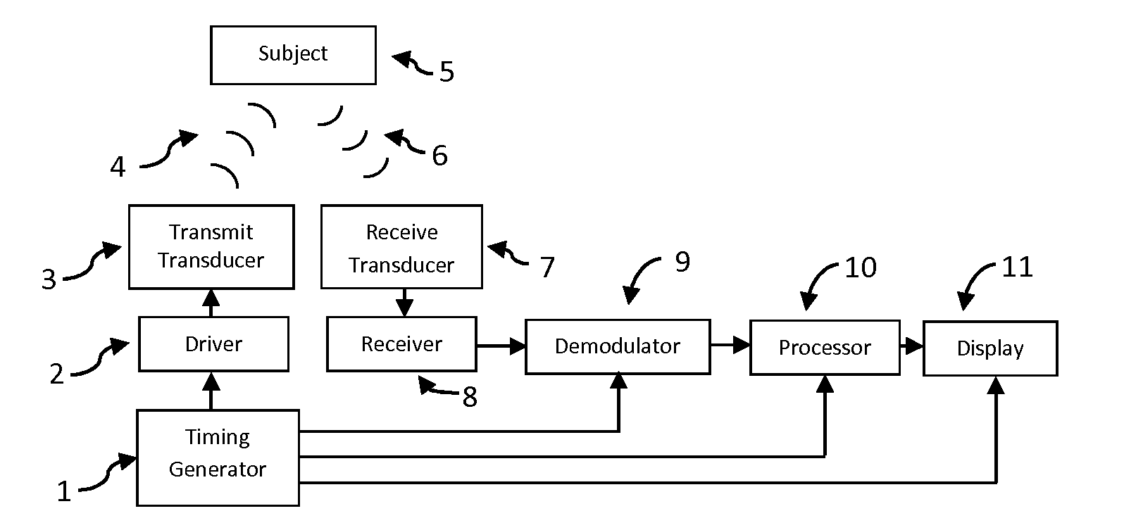
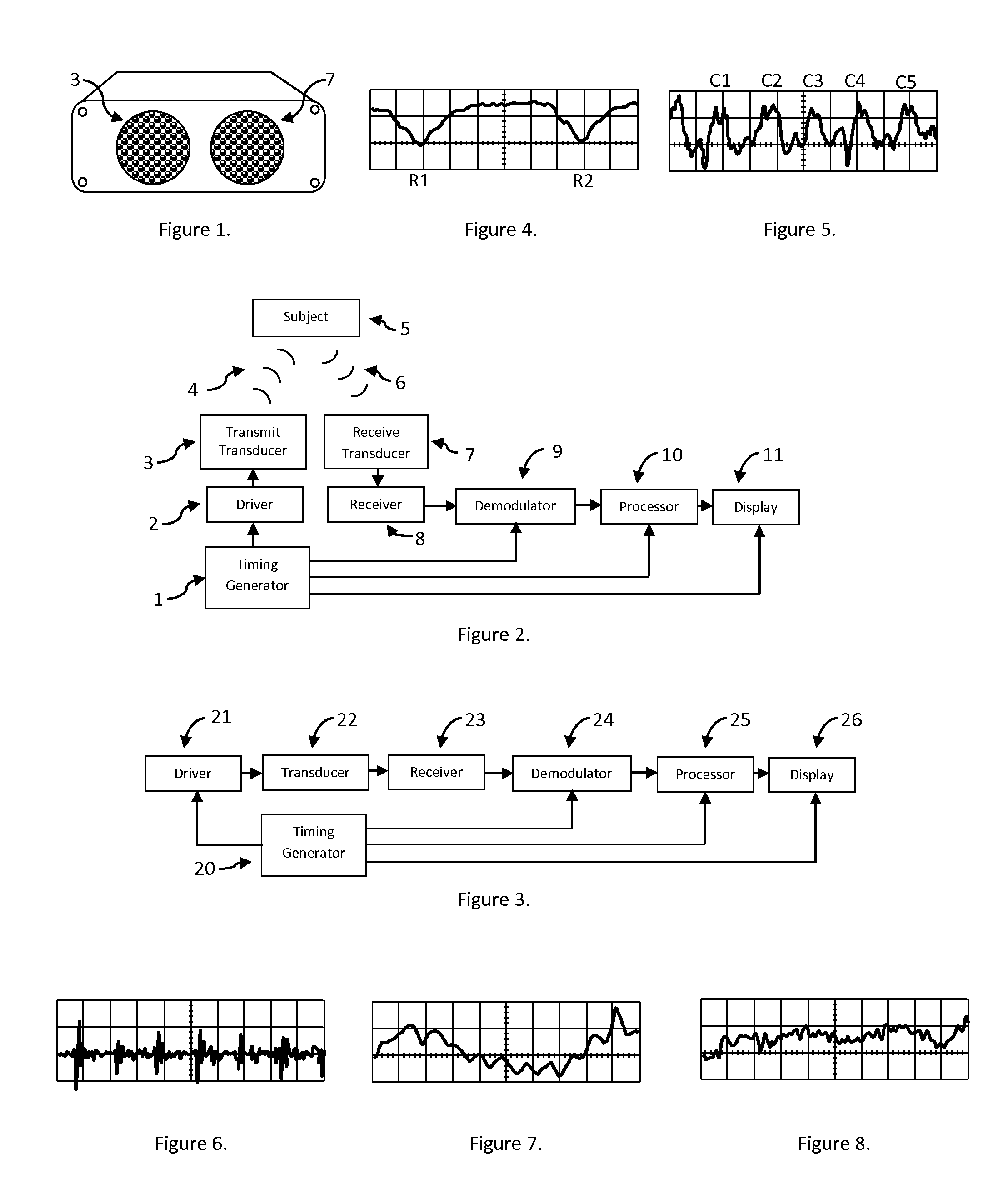
[0044]FIG. 1 illustrates one embodiment of the biometric monitoring system preferably comprising a pair of ultrasonic transducers, wherein the transducers may be made from piezo-ceramics (e.g., lead metaniobate or lead-zirconate-titanate), piezo-polymers (polyvinylidene-fluoride) or other materials. In one preferred configuration, the pair of ultrasonic transducers may be of an electrostatic type, as described by, Muggli, et al., in U.S. Pat. No. 4,081,626 [10]; by Paglia in U.S. Pat. No. 4,085,297 [11]; and / or by Kirby, et al., in U.S. Pat. No. 4,872,148 [1...


PUM


Abstract

A non-contact system utilizing an air-propagated ultrasound for monitoring biometric parameters is disclosed. A non-contact sensor transmits an ultrasonic wave toward a subject. The wave is reflected by the subject's skin surface back toward the sensor. Electronics in the sensor measure the small changes in displacement of the skin surface to derive a plurality of biometric parameters, including but not limited to respiration rate, heart rate, eye motion, and limb movement.

Description

CROSS REFERENCE TO RELATED APPLICATION[0001]This application takes priority from and claims the benefit of Provisional Application Ser. No. 61 / 338,738 filed on Feb. 24, 2010 the contents of which are hereby incorporated by reference.BACKGROUND OF THE INVENTION[0002]1. Field of the Invention[0003]This invention relates generally to monitoring systems, and more particularly to portable, non-contact, non-invasive monitoring systems preferably for assessing a plurality of biometric information, including but not limited to respiratory parameters, cardiac parameters, ocular motion during sleep, and / or limb movement.[0004]2. Description of the Related Art[0005]The use of Doppler radar techniques to monitor subjects has been described in the literature. Some of the earliest work on the use of continuous wave (CW) Doppler radar to detect cardiopulmonary signals was done in the 1980s at the University of Illinois [2] using 10 GHz radar. In 2001, Lohman, et al., described signal processing te...

Claims


Application Information

Patent Timeline
IPC IPC(8): A61B8/00
CPCA61B5/021A61B5/7239A61B5/1135A61B5/02444A61B8/02A61B8/5207A61B8/5223
Inventor HAASE, WAYNE C.HAASE, ZACHARY S.YOUNG, RICHARD F.MONIN, PHILIPPE E.MCCARTHY, COLIN W.SARLES, F. WILLIAM
Owner SUMMIT INDS
Why Eureka
Try Eureka