Reconfigurable Photovoltaic Structure

Inactive Publication Date: 2012-05-10
SHAMSELDEIN MOHAMED ZAKARIA MOHAMED AHMED +2
View PDF1 Cites 10 Cited by
  • Summary
  • Abstract
  • Description
  • Claims
  • Application Information

AI Technical Summary

Benefits of technology

[0021]In yet another aspect, an irradiance level sensor for a photovoltaic element is provided, the irradiance level sensor comprising one or more imaging device operable to determine an irradiance pattern coupled to an irradiance level calibrator operable to correlate said irradiance pattern with an irradiance level for said photovoltaic element.
[0022]In a still further aspect, a method of detecting a fault in a total

Problems solved by technology

The use of PV structures for power generation brings many challenges, one of which is partial shading loss.
For example, it has been shown that a neighbouring building, tree or passing clouds can cause a PV structure to have an annual loss up to 10%
Partial shading causes the output of even the unshaded parts of the PV structure to decrease since a partially shaded PV structure has a mismatch between its constituent PV elements.
This style of connection reduces the overall effect of mismatch in the PV system but is still affected by partial shading loss.
However, these diodes create multiple power peaks which increase the complexity of the Maximum Power Point Tracking (MPPT).
The increased complexity of MPPT may lead to an operation that is not optimized at the maximum power point.
Bypass diodes, furthermore, do not solve the problem of reduction in generated power.
However, partial shading losses from unpredictable sources

Method used


Image

  • Reconfigurable Photovoltaic Structure
  • Reconfigurable Photovoltaic Structure
  • Reconfigurable Photovoltaic Structure

Examples


Embodiment Construction

[0053]The present invention provides a reconfigurable PV structure. The reconfigurable PV structure can be used to reduce mismatch. Mismatch can, for example, be caused by partial shading loss. The invention can reduce mismatch in the PV structure due to both predictable and unpredictable sources. It can also be used to locate or isolate faults in the PV structure and reduce the effects of these faults.

[0054]A PV structure as described herein comprises a plurality of PV elements. The PV elements could be PV cells, PV modules, PV panels, PV arrays, PV farm fields, PV farms, or any combination thereof.

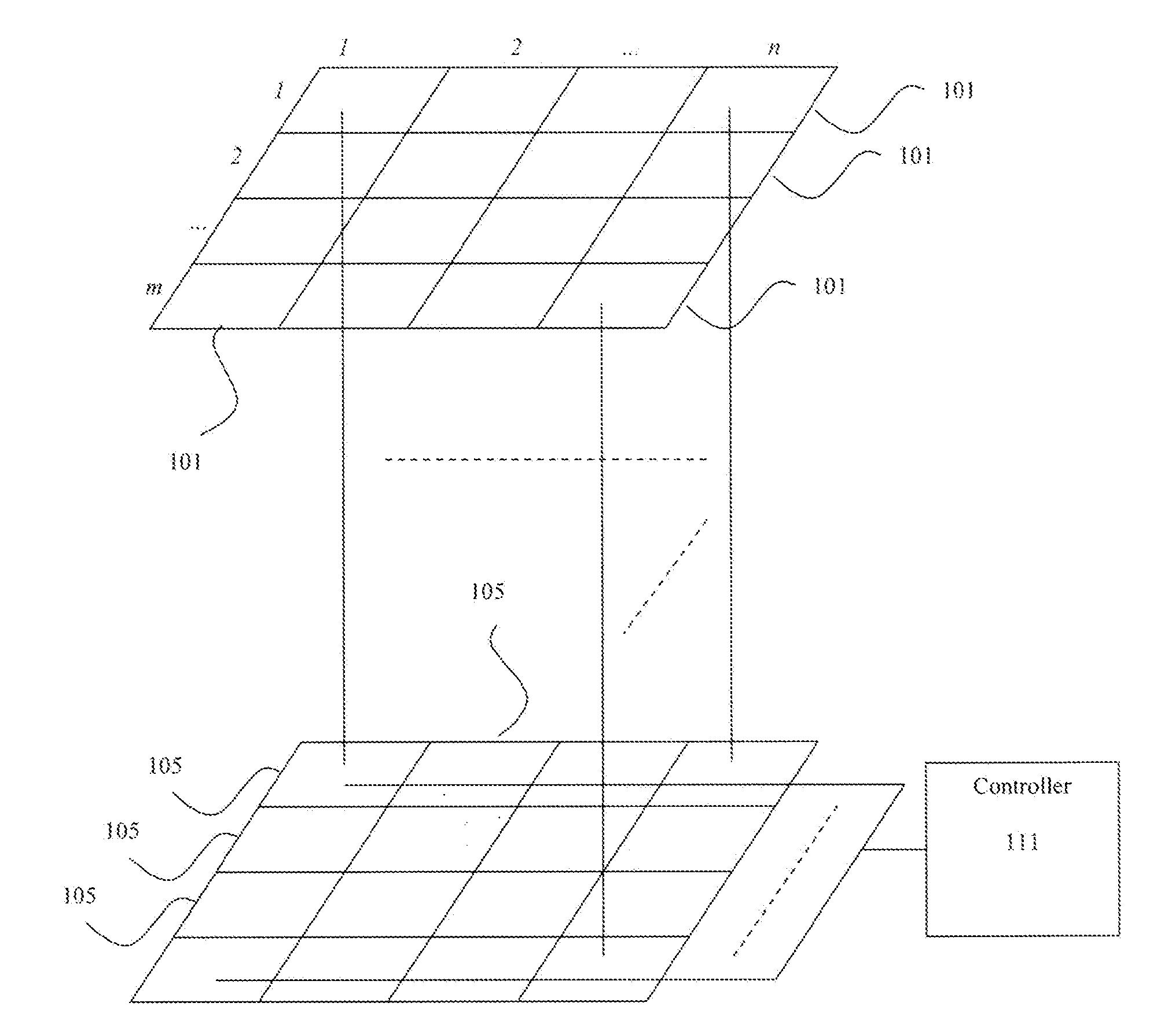
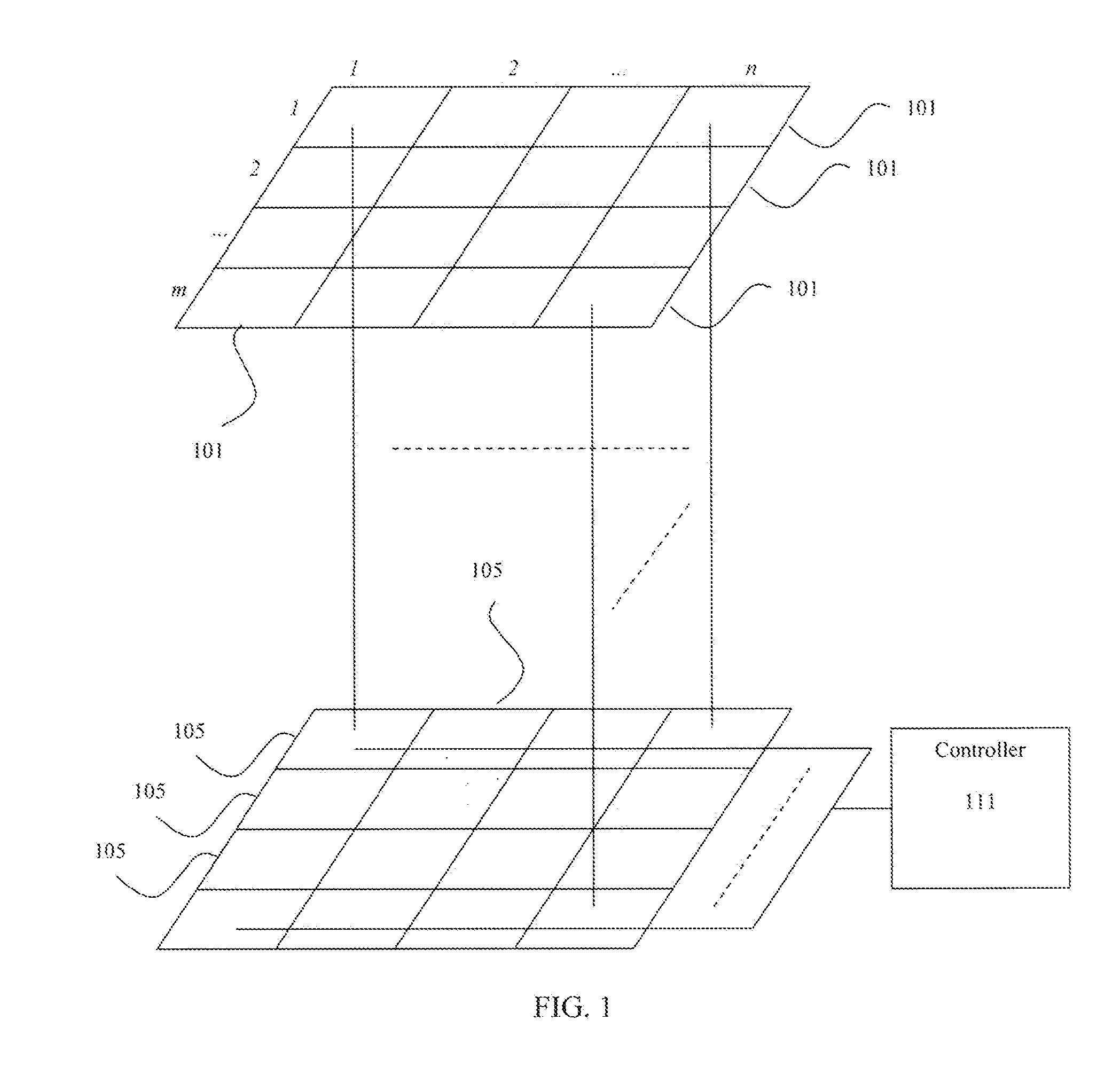
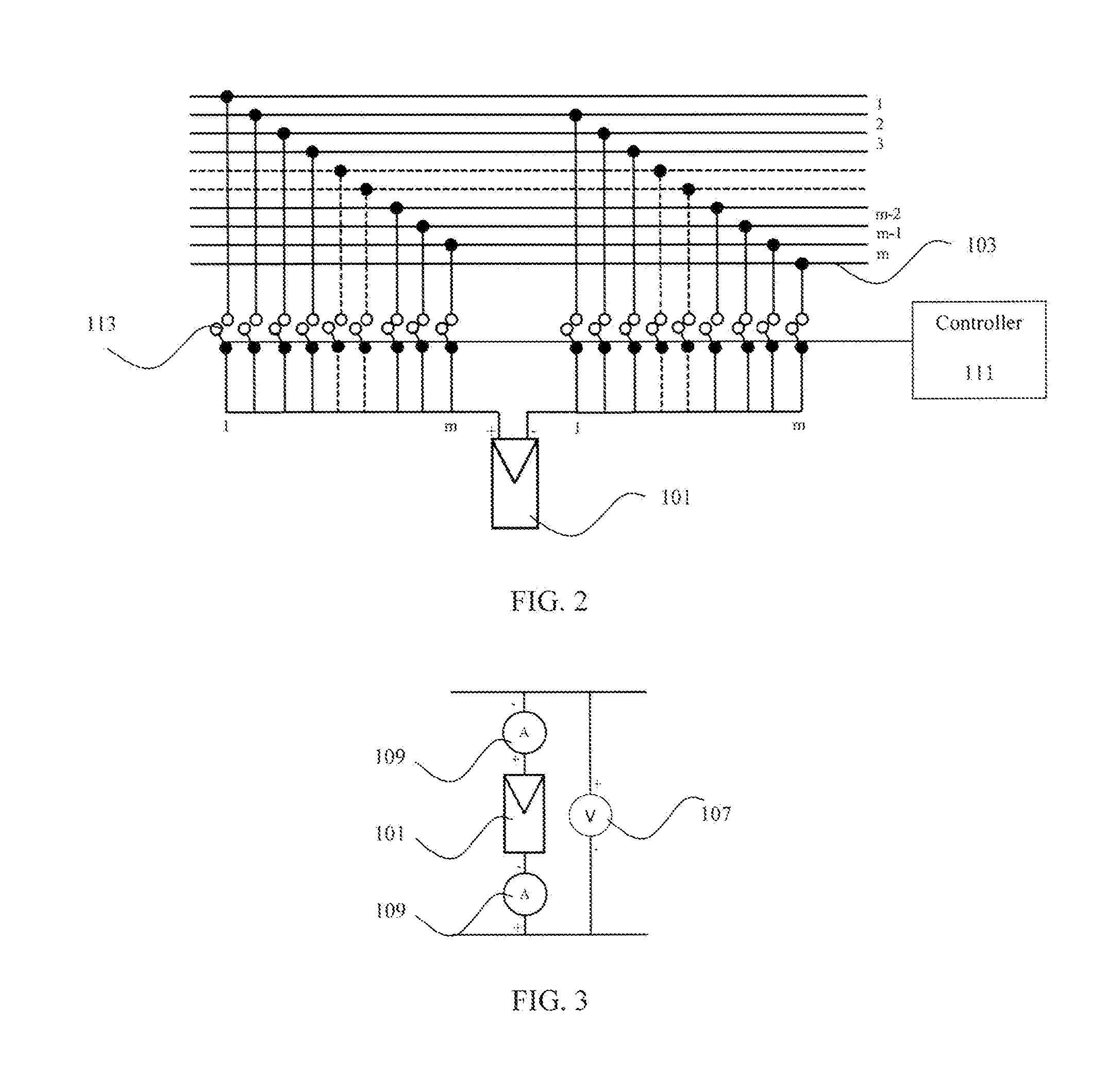
[0055]Referring therefore to FIGS. 1 to 4, a reconfigurable PV structure in accordance with the present invention comprises a plurality of PV elements 101 physically arranged in m rows and n columns. m+1 electrical conductors 103, such as wires or PCB traces for example, are provided for the m rows but it is not necessarily the case that PV elements physically arranged in a particular ro...


PUM


Abstract

A photovoltaic structure is provided. The photovoltaic structure has photovoltaic elements that can be electrically connected to one another to reduce mismatch. The photovoltaic elements can be electrically connected based on sorting the photovoltaic elements by irradiance level, minimizing mismatch, or maximizing output power. Where sorting is used, the photovoltaic elements can be connected in a serpentine arrangement.

Description

PRIORITY CLAIM[0001]This application is a continuation of PCT Patent Application No. PCT / CA2011 / 000809, filed Jul. 13, 2011 which claims priority from U.S. Provisional Patent Application No. 61 / 365,223 filed Jul. 16, 2010, both of which are incorporated herein by reference.FIELD OF THE INVENTION[0002]The present invention relates generally to a reconfigurable photovoltaic structure.DESCRIPTION OF THE PRIOR ART[0003]Increase in oil prices, depletion of fossil fuel reservoirs, energy security concerns and global warming have been the most important motives behind the use of renewable energy for power generation, including solar energy. Energy from solar can be generated using photovoltaic (PV) structures. PV structures are expected to play a major role in smart grids as a distributed generation or as a power plant.[0004]The use of PV structures for power generation brings many challenges, one of which is partial shading loss. Partial shading loss occurs when a part of a PV structure i...

Claims


Application Information

Patent Timeline
IPC IPC(8): H01L31/02H01L31/18
CPCY02E10/50H01L31/0504
Inventor SHAMSELDEIN, MOHAMED ZAKARIA MOHAMED AHMEDKAZERANI, MEHRDADSALAMA, MAGDY
Owner SHAMSELDEIN MOHAMED ZAKARIA MOHAMED AHMED
Why Eureka
Try Eureka