Supercharge Your Innovation With Domain-Expert AI Agents!

Clutch release bearing device

a technology of bearings and clutches, which is applied in the direction of mechanical actuated clutches, interlocking clutches, couplings, etc., can solve the problems of axial bulky clutch bearings, high number of pieces that comprise such devices, and considerable assembly costs, and achieves simple structure and easy manipulation and mounting.

Inactive Publication Date: 2011-02-01
AB SKF
View PDF95 Cites 6 Cited by
  • Summary
  • Abstract
  • Description
  • Claims
  • Application Information

AI Technical Summary

Benefits of technology

The design provides an economical, easy-to-assemble clutch release bearing with excellent transverse sealing that maintains effectiveness during self-centering and radial movement, while minimizing axial bulk and assembly costs.

Problems solved by technology

The number of pieces that comprise such a device is quite high which involves considerable assembly costs.
Such a clutch bearing is axially bulky while being costly and difficult to assemble.

Method used


Image

  • Clutch release bearing device
  • Clutch release bearing device
  • Clutch release bearing device

Examples


Embodiment Construction

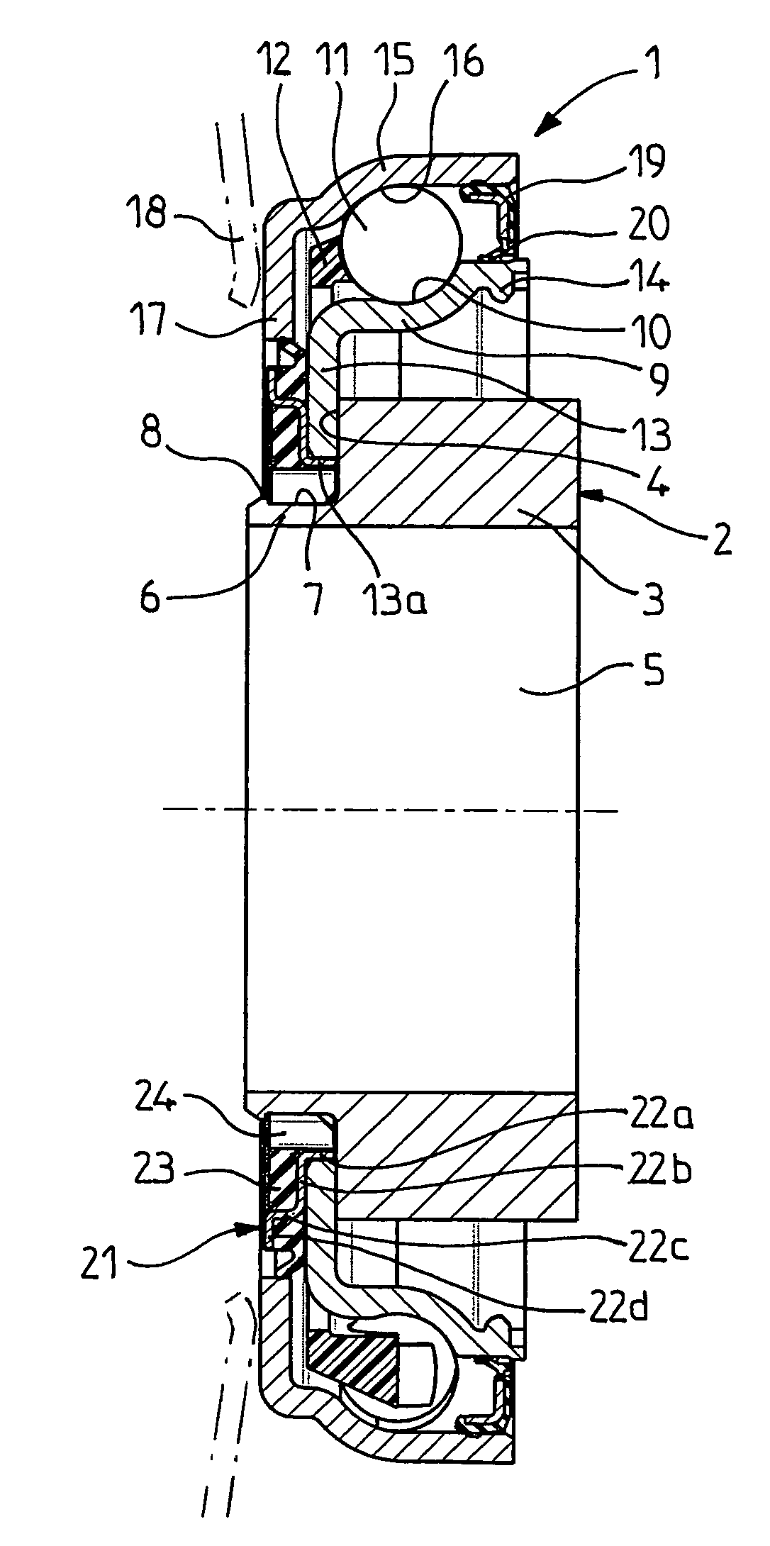
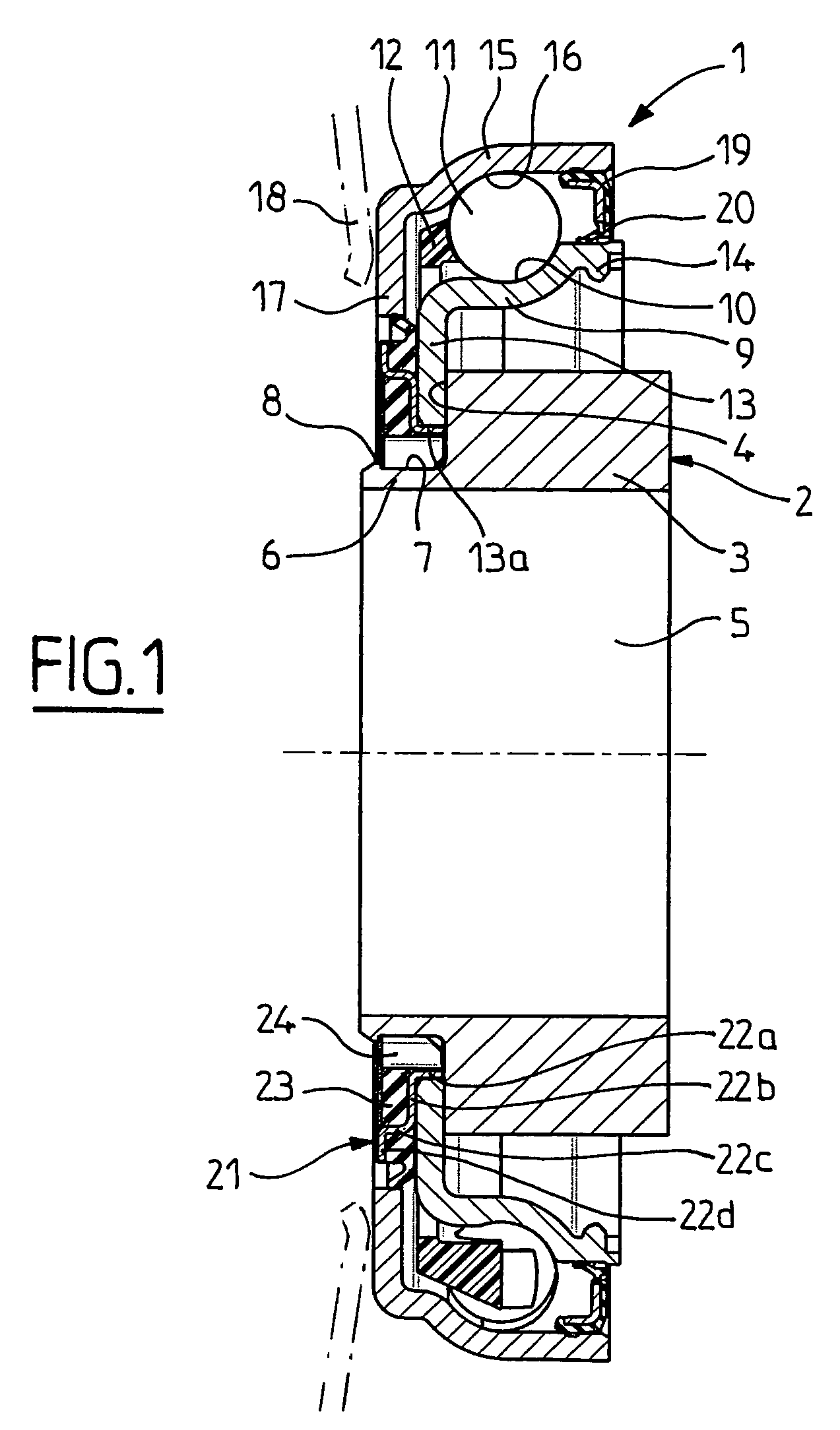
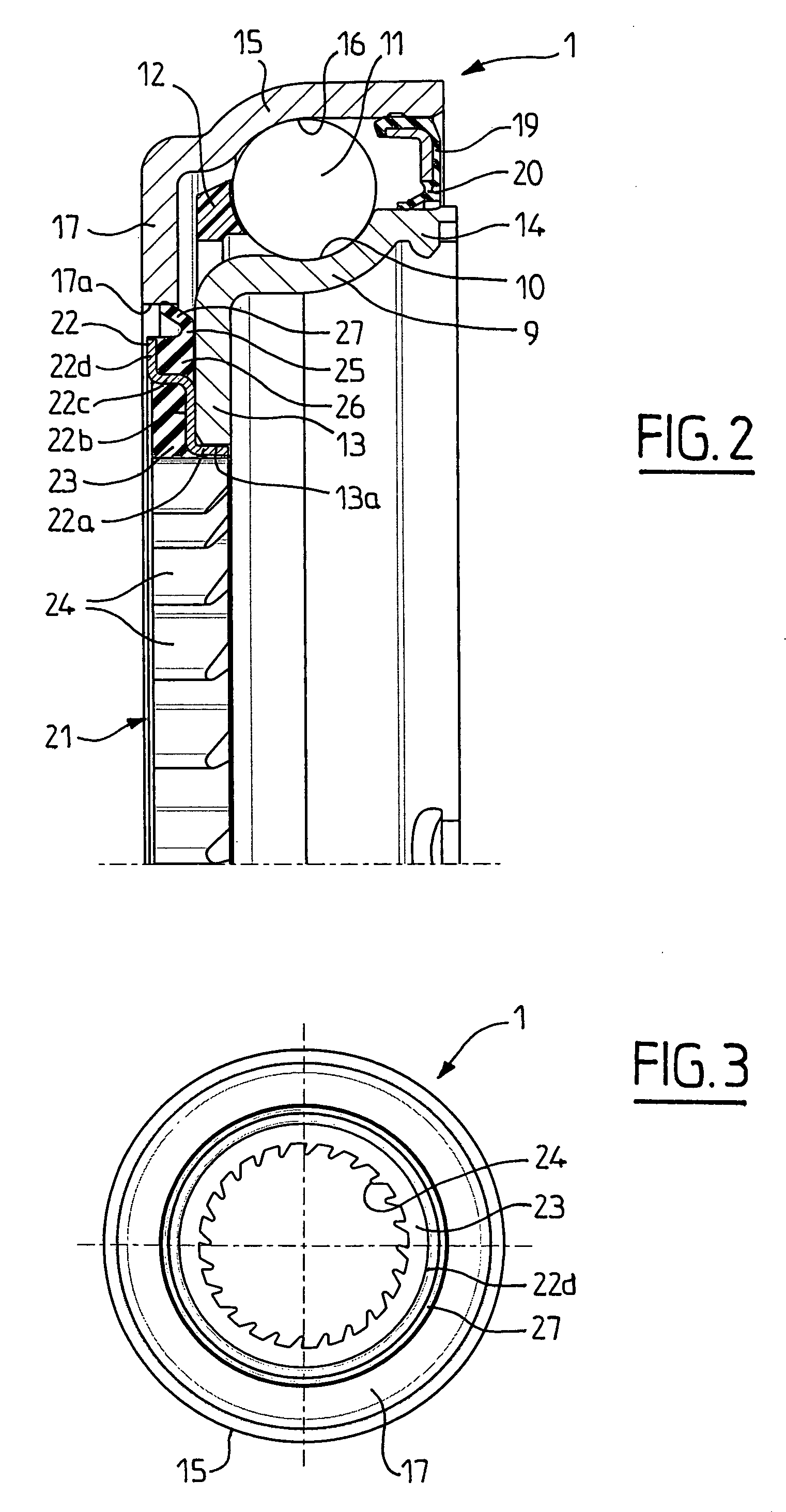
[0027]As illustrated in FIGS. 1 to 3, the clutch release bearing includes a rolling bearing 1 mounted on an operating element 2, advantageously made of synthetic material and including a cylindrical body 3 and a radial bearing surface 4. The operating element 2 may for example have the shape of a piston of a hydraulic clutch-operating device or of a separate push rod axially extending the said piston. The operating element 2 is usually mounted by its bore 5 onto a stationary guide-tube not shown, while the said operating element 2 is capable of moving in translation along the axis of the guide-tube. A free end of the operating element 2 includes a cylindrical portion 6 of lesser thickness than the cylindrical body 3 and provided with an outer surface 7. The radial bearing surface 4 is placed axially between the cylindrical body 3 and the cylindrical portion 6. A retention element 8 in the form of an annular rib facing outwards is formed on the outer surface 7 axially opposite the ra...


PUM


Abstract

Clutch release bearing device, including an operating element, a rolling bearing furnished with rolling elements, with a non-rotating ring provided with a radial portion facing inwards and having a central opening, and with a rotating ring, the said rolling bearing being mounted on the operating element with which it may move axially, and a self-alignment sleeve placed between the non-rotating ring and the operating element and provided with a plurality of elastic ribs facing inwards.

Description

BACKGROUND OF THE INVENTION[0001]1. Field of the Invention[0002]The present invention relates to the field of clutch release bearings, in particular for automobiles, of the type including a thrust rolling bearing mounted on an operating element.[0003]2. Description of the Relevant Art[0004]French document No. 2 819 864 is known to describe a clutch release bearing including a leading element mounted on an operating element. The leading element includes a bearing provided with a rotating ring and a non-rotating ring capable of moving radially relative to the operating element for its self-alignment relative to the clutch diaphragm. The non-rotating ring includes a radial portion facing inwards. The device includes a means of axially interlocking the leading element on the operating element in the form of a lock washer. The device includes a self-alignment element in the form of a sheet metal piece, centered on the non-rotating ring and provided with axially elastic tabs, such that th...

Claims


Application Information

Patent Timeline
Patent Type & Authority Patents(United States)
IPC IPC(8): F16C19/10F16D19/00F16C23/08F16C32/06F16D23/14
CPCF16C19/163F16C33/783F16C33/7886F16C33/7889F16D23/142F16C2361/43F16D2300/08
Inventor ARNAULT, BENO TCOLLOGNAT, JEAN-PIERRE
Owner AB SKF
Features
  • R&D
  • Intellectual Property
  • Life Sciences
  • Materials
  • Tech Scout
  • Unparalleled Data Quality
  • Higher Quality Content
  • 60% Fewer Hallucinations
Learn More