Engine control system

a control system and engine technology, applied in the direction of electric control, charge feed system, speed sensing governor, etc., can solve the problems of difficulty in meticulous control, low air/fuel ratio, operational disorder or increase of fuel consumption, etc., and achieve the effect of simple structur

US7950366B2Active Publication Date: 2011-05-31HONDA MOTOR CO LTD
20 Cites 19 Cited by

Patent Information

Authority / Receiving Office
US · United States
Patent Type
Patents(United States)
Current Assignee / Owner
Publication Date
2011-05-31

Smart Images

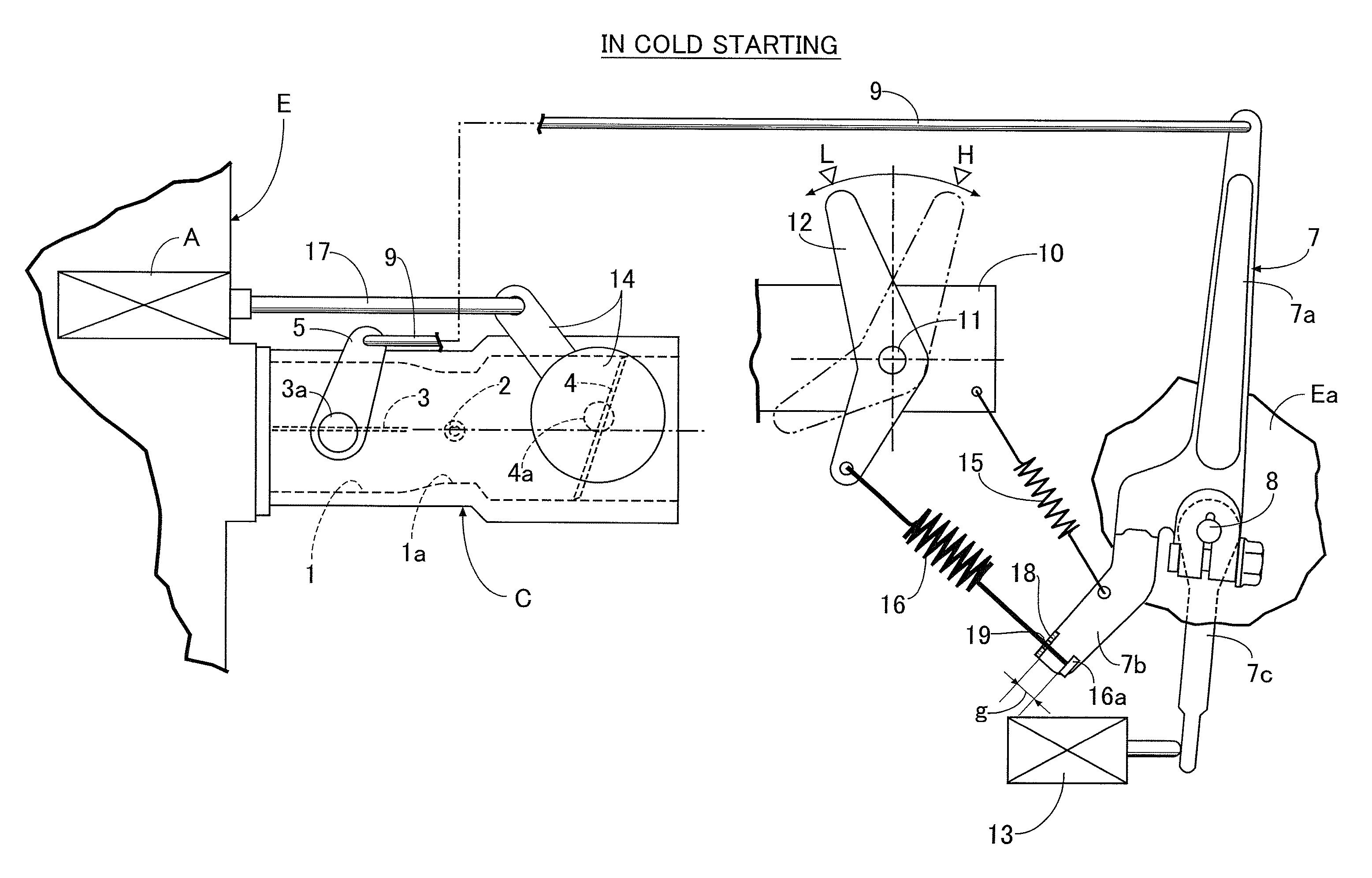
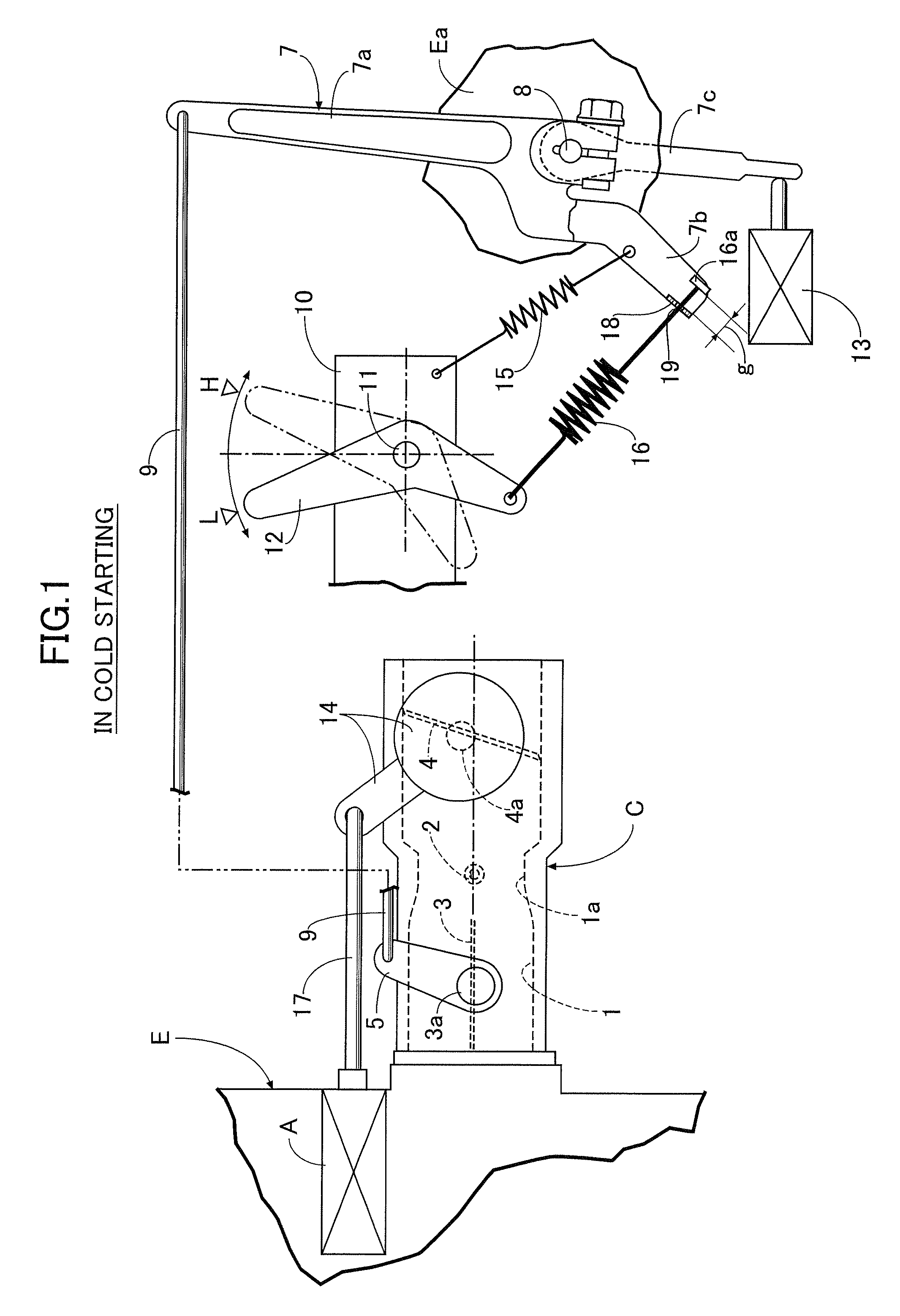
  • Figure 1
    Figure 1
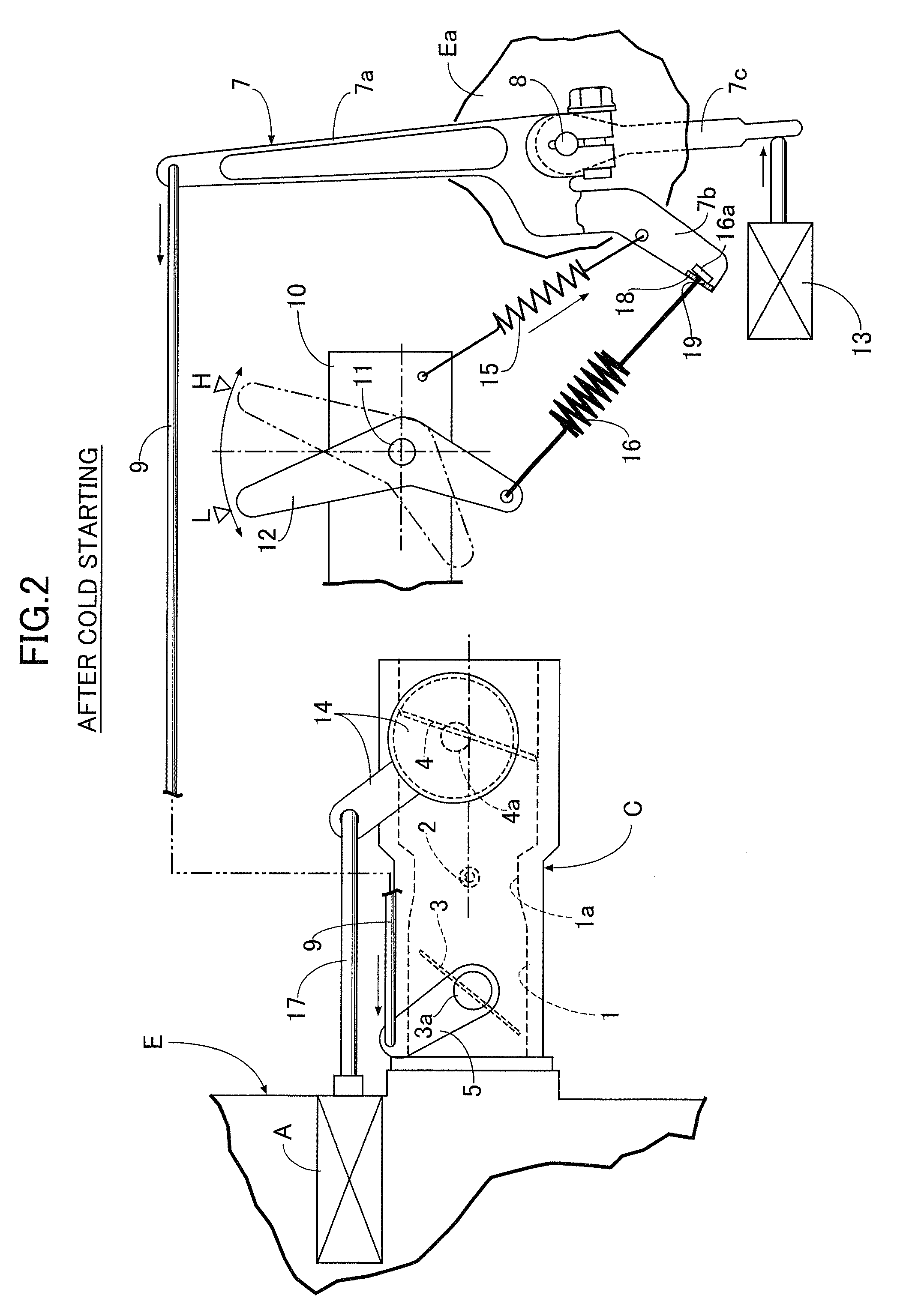
  • Figure 2
    Figure 2
  • Figure 3
    Figure 3
Patent Text Reader

Abstract

An engine control device includes a governor lever, a centrifugal governor, a control lever operated to oscillate between a low-speed position and a high-speed position, and a governor spring expandedly provided between the control lever and the governor lever. An automatic choke device is connected to a choke valve of a carburetor. A play is provided between the governor lever and the governor spring. The play holds the governor spring in a free state during rotation of the control lever from the low-speed position to the high-speed position by a predetermined angle. A subsidiary spring is provided between a fixed structure and the governor lever so as to constantly urge the governor lever in a direction to open the throttle valve. A spring constant of the subsidiary spring is smaller than that of the governor spring. Thus, there is provided the engine control system with the automatic choke device, which can meticulously control an air / fuel ratio from start of an engine to under-load operation of the engine in accordance with increase and decrease in temperature of the engine.
Need to check novelty before this filing date? Find Prior Art

Description

RELATED APPLICATION DATA

[0001] The Japanese priority application No. 2007-31401 upon which the present application is based is hereby incorporated in its entirety herein by reference.BACKGROUND OF THE INVENTION

[0002] 1. Field of the Invention

[0003] The present invention mainly relates to an engine control system used in control of a rotational speed of a general-purpose engine having a small engine displacement, and particularly relates to an engine control system comprising: a governor lever which is oscillatably supported around an axis on an engine body, and connected to a throttle valve of a carburetor; a governor which increases a thrust for rotating the governor lever in a direction to close the throttle valve in accordance with an increase in an engine rotational speed; a control lever which is supported around an axis on a fixed structure, and operated to oscillate between a low-speed position and a high-speed position; a governor spring which is expandedly provided between the...

Examples

Embodiment Construction

[0022]First, in FIG. 1, a reference character E denotes a 4-cycle general-purpose engine serving as a power source for various work machines. An carburetor C is mounted on one side face of a cylinder head of the engine E. The carburetor C has an intake path 1 leading to an intake port of the engine E. A throttle valve 3 and a choke valve 4 are provided on a downstream side and an upstream side, respectively, of a venturi portion 1a provided in the intake path 1 at an intermediate position therebetween. A fuel nozzle 2 is open at the venturi portion 1a.

[0023]A throttle lever 5 is secured to an outer end of a valve shaft 3a of the throttle valve 3. The throttle lever 5 is rotated to open and close the throttle valve 3.

[0024]A governor lever 7 is provided through a pivotal shaft 8 on an engine body Ea including a crank case and other components of the engine E. The governor lever 7 has three arms, that is, first, second and third arms 7a, 7b and 7c. The first arm 7a is connected throu...