Turbine blade with multiple trailing edge cooling slots

a technology of turbine blades and cooling slots, which is applied in the field of cooling systems of turbine blades, can solve the problems of reducing stage performance, high aerodynamic blockage, and one of the more challenging sections of turbine blade cooling, so as to reduce the effective thickness of airfoil trailing edges, reduce the temperature of trailing edges, and reduce the heat load in the base region

Inactive Publication Date: 2011-12-20
SIEMENS ENERGY INC
View PDF26 Cites 14 Cited by
  • Summary
  • Abstract
  • Description
  • Claims
  • Application Information

AI Technical Summary

Benefits of technology

[0008]The interconnecting boundary layer bleed hole preferably extends from the curved rearward side of the pressure side cooling slot to at least one of the suction side cooling slots. The boundary layer bleed hole can be oriented relative to the convex suction side of the airfoil so that cooling flow in the suction side cooling slot is concurrent with the mainstream flow along the suction side, whereby shear mixing between the mainstream flow and the cooling flow is reduced. The profile shape of each suction side cooling slot can also be oriented relative to the convex suction side so that cooling flow in the suction side cooling slot is concurrent with the mainstream flow along the suction side to reduce this shear mixing.
[0011]An advantage of this invention is that multiple suction side cooling slots reduce the airfoil trailing edge effective thickness, thus reducing base region heat load, resulting in reduced trailing edge metal temperature and improved airfoil life. A reduced trailing edge thickness can also reduce airfoil blockage and minimize stage pressure losses, translating into improved turbine stage performance.
[0012]Another advantage is that the suction side submerged cooling slots provide additional convective cooling for the trailing edge corner, thus minimizing hot spots in this region of the airfoil. The relatively increased depth of the submerged cooling slots can lower the cooling air velocity and yield good downstream film effectiveness. This slot design can also minimize shear mixing, thus lowering aerodynamic loss and maintain high film cooling effectiveness for the suction side surface of the airfoil. This design also reduces pressure side cut back, thus minimizing shear mixing and increasing film effectiveness on the pressure side.

Problems solved by technology

Size and space limitations make trailing edges one of the more challenging sections of a turbine blade to cool.
Such design requires a thicker trailing edge that can induce higher aerodynamic blockage and reduce stage performance.
However, the pressure side bleed cooling approach causes a side flow and presents shear mixing between the cooling air and the mainstream flow as the cooling air exits the pressure side channel outlet.
The shear mixing of the cooling air with the mainstream flow reduces cooling effectiveness of the trailing edge overhang, thus inducing over temperature or a hot spot at the trailing edge suction side location.
Frequently, a hot spot can become the life limiting location for the entire airfoil.

Method used


Image

  • Turbine blade with multiple trailing edge cooling slots
  • Turbine blade with multiple trailing edge cooling slots
  • Turbine blade with multiple trailing edge cooling slots

Examples


Embodiment Construction

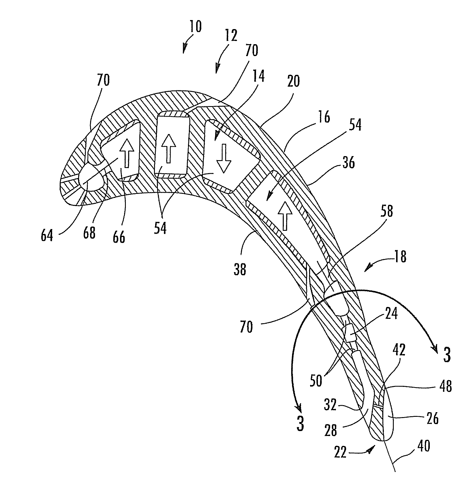
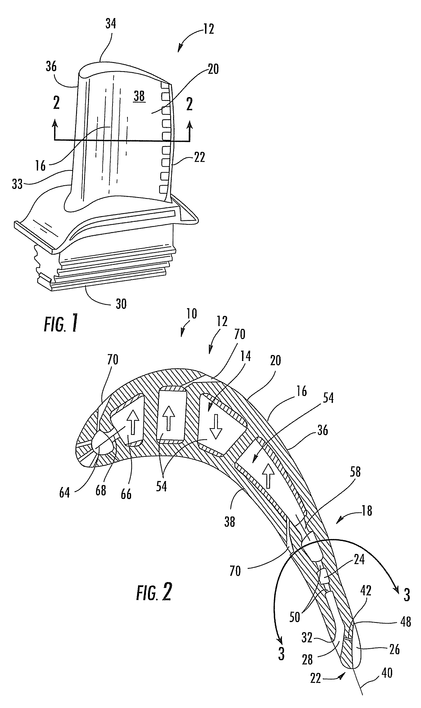
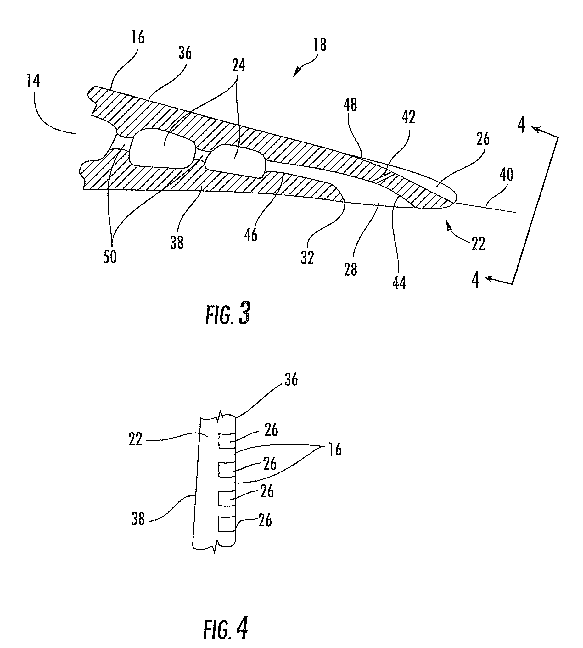
[0019]As shown in FIGS. 1-4, the invention is directed to a turbine airfoil cooling system 10 for a turbine airfoil 12 used in turbine engines. In particular, the turbine airfoil cooling system 10 may include one or more internal cavities 14, as shown in FIGS. 2 and 3, positioned between outer walls 16 of a generally elongated, hollow airfoil body 20 of the turbine airfoil 12. The cooling system 10 may include one or more trailing edge cooling channels 18 positioned within the generally elongated, hollow airfoil body 20.

[0020]The turbine blade into which the cooling system is integrated can have a general overall construction similar to existing turbine blades, and made from conventional alloys or similar materials. The turbine blade can have application, for example, in a first stage of a turbine engine. As shown in FIG. 1, the airfoil 12 can have a hollow airfoil body 20 generally elongated span wise, and the outer wall 16 can extend chord wise from a forward leading edge 33 to a ...


PUM


Abstract

A cooling system for a turbine airfoil of a turbine engine has a multiple suction side cooling slots extending from a front edge on the suction side to the center of the trailing edge or even to the pressure side of the center line and a pressure side cooling slot curving to a pressure side outlet forward of the trailing edge and having a front pressure side lip that is aligned with or forward of the front edge of the suction side cooling slots. The suction side cooling slots receive cooling flow from the pressure side cooling slots through a boundary layer bleed valve, which is also aligned with or rearward of the pressure side lip. The cooling system may also combine double impingement cooling with these features. The cooling system minimizes shear mixing, reduces hot spots and can reduce the trailing edge thickness, resulting in more efficient stage performance and extended operational life.

Description

FIELD OF THE INVENTION[0001]This invention is directed generally to turbine airfoils, and more particularly to cooling systems in hollow turbine airfoils.BACKGROUND[0002]Typically, gas turbine engines include a compressor for compressing air, a combustor for mixing the compressed air with fuel and igniting the mixture, and a turbine blade assembly for producing power. Combustors often operate at high temperatures that may exceed 2,500 degrees Fahrenheit. Typical turbine combustor configurations expose turbine blade assemblies to these high temperatures. As a result, turbine blades must be made of materials capable of withstanding such high temperatures. In addition, turbine blades often contain cooling systems for prolonging the life of the blades and reducing the likelihood of failure as a result of excessive temperatures, particularly in concentrated areas of over temperature, sometimes referred to as hot spots.[0003]Typically, turbine blades are formed from a root portion having ...

Claims


Application Information

Patent Timeline
Patent Type & Authority Patents(United States)
IPC IPC(8): F01D5/18F01D5/08F01D5/20
CPCF01D5/187F05D2240/122F05D2240/304F05D2250/71F05D2260/202F05D2260/22141
Inventor LIANG, GEORGE
Owner SIEMENS ENERGY INC
Why Eureka
Try Eureka