Method and apparatus for controlling electronic appliance

a technology for electronic appliances and control methods, applied in the field of electronic appliances, can solve problems such as troublesome user experience, troublesome user experience, and inability to correctly detect an objective control button

Active Publication Date: 2012-03-27
JVC KENWOOD CORP
View PDF25 Cites 29 Cited by
  • Summary
  • Abstract
  • Description
  • Claims
  • Application Information

AI Technical Summary

Benefits of technology

[0019]In this way, the present invention can surely detect an operation conducted by an operator with respect to one of control zones or control buttons displayed on a display.

Problems solved by technology

Manipulating a number of keys is troublesome for the user.
This is also troublesome for the user.
The related art, however, is not good at correctly detecting an objective control button specified by a hand of the user on the display if the hand is over a plurality of control buttons including the objective control button, or if the hand and other objects such as the head of the user are superimposed on a plurality of control buttons including the objective control button.

Method used


Image

  • Method and apparatus for controlling electronic appliance
  • Method and apparatus for controlling electronic appliance
  • Method and apparatus for controlling electronic appliance

Examples


example 1

[0140]As explained above, the detection signals B[5] and B[9] shown in (A) of FIG. 15 have different amplitudes, and therefore, are usable to determine an objective control button (5) from among the control buttons 5 and 9. If a plurality of detection signals have the same amplitude, there is a possibility of selecting a plurality of objective control buttons.

[0141]Example 1 according to the present invention is a technique of selecting one control button from among a plurality of control buttons on which the hand of the user 3 is placed.

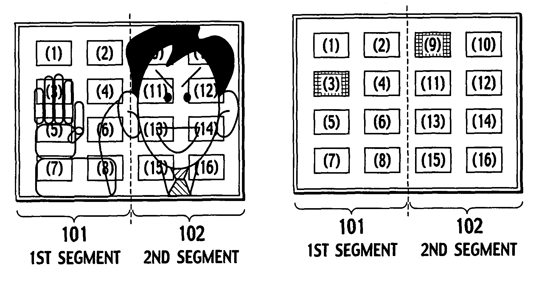
[0142]FIG. 17A shows a user's hand overlaid on control buttons 5, 9, and 13 like FIG. 14A. Among the control buttons 5, 9, and 13, the control button 5 is an objective control button in Example 1.

[0143]FIG. 17B shows the control button 5 activated according to Example 1.

[0144]Among the control buttons on which the user's hand is overlaid, Example 1 activates a control button (the control button 5) that is at an uppermost position on the display 21. ...

example 2

[0169]Example 2 according to the present invention is another technique of selecting one control button from among a plurality of control buttons on which the user 3 is superimposed. In Example 2, not only the hand of the user 3 but also the face of the user 3 are superimposed on a plurality of control buttons including the control button 5 that is an objective control button.

[0170]The object extractor 30 extracts objects according to specific colors, gradation levels, and move, and therefore, detects the face as well as the hand. According to Example 1, an active flag having a smallest button number is selected from among high-level active flags F[i]. Accordingly, in the case of FIG. 21A, the active flag F[3] of the control button 3 is selected as shown in FIG. 21B. This is because the face of the user 3 is superimposed on the control buttons as shown in FIG. 21A. If this happens, the active flag of the objective control button 5 intended by the user 3 will not become high.

[0171]As...


PUM


Abstract

An apparatus for controlling an electronic appliance having a display is provided. A plurality of control buttons are displayed on the display. An operator in front of the display is photographed with a video camera and is displayed on the display. The operator holds his or her hand to specify one of the control buttons on the display. The control buttons are provided with numbers or marks according to the order of priority. A feature detector of the apparatus detects various features from the photographed image. According to the features, a controller of the apparatus selects one of the control buttons on which the hand of the operator is superimposed and carries out an operation corresponding to the selected control button with respect to the electronic appliance.

Description

BACKGROUND OF THE INVENTION[0001]1. Field of the Invention[0002]The present invention relates to an electronic appliance having a display, such as a television set and a personal computer, provided with an improved remote control function, and particularly, to a method of and an apparatus for controlling such an electronic appliance.[0003]2. Description of Related Art[0004]In the 1980s, infrared remote controllers started to be attached to home appliances such as television sets. The remote controllers have widely accepted and greatly changed the usage of home appliances. At present, controlling electronic appliances with remote controllers is in the mainstream. The remote controller basically employs a one-key (one-button), one-function operation. A remote controller for the television set, for example, has ON / OFF, CHANNEL, VOLUME, and INPUT SELECT keys for conducting respectively assigned functions. The remote controller is very useful for remotely controlling the television set a...

Claims


Application Information

Patent Timeline
Patent Type & Authority Patents(United States)
IPC IPC(8): G09G5/00H04N5/232G06F3/041
CPCG06F3/0304G06F3/0346G06F3/0481
Inventor KITAURA, MASAHIRO
Owner JVC KENWOOD CORP
Why Eureka
Try Eureka