
Touch sensor

a technology of touch sensor and sensor body, which is applied in the field of touch sensor, can solve the problems of hardly being able to detect the detection sensitivity of the touch of the finger or the like largely degrades, etc., and achieves the effect of improving the sensitivity of pressure detection and high translucency

Active Publication Date: 2016-07-07
MURATA MFG CO LTD
View PDF8 Cites 10 Cited by
  • Summary
  • Abstract
  • Description
  • Claims
  • Application Information

AI Technical Summary

Benefits of technology

The present invention provides a touch sensor that can better detect when someone touches the surface it is placed on. This is achieved by using a piezoelectric film with a detecting electrode formed in an insulating film to make the pressure detection sensor easier to create. The sensor is also highly transparent and sensitive to pressure detection.

Problems solved by technology

Therefore, the piezoelectric detecting electrode acts as an electromagnetic shield against the electrostatic type position detection sensor, and detection sensitivity of the touch of the finger or the like largely degrades, or the touch of the finger or the like can hardly be detected.

Method used


Image

  • Touch sensor
  • Touch sensor
  • Touch sensor

Examples


first embodiment

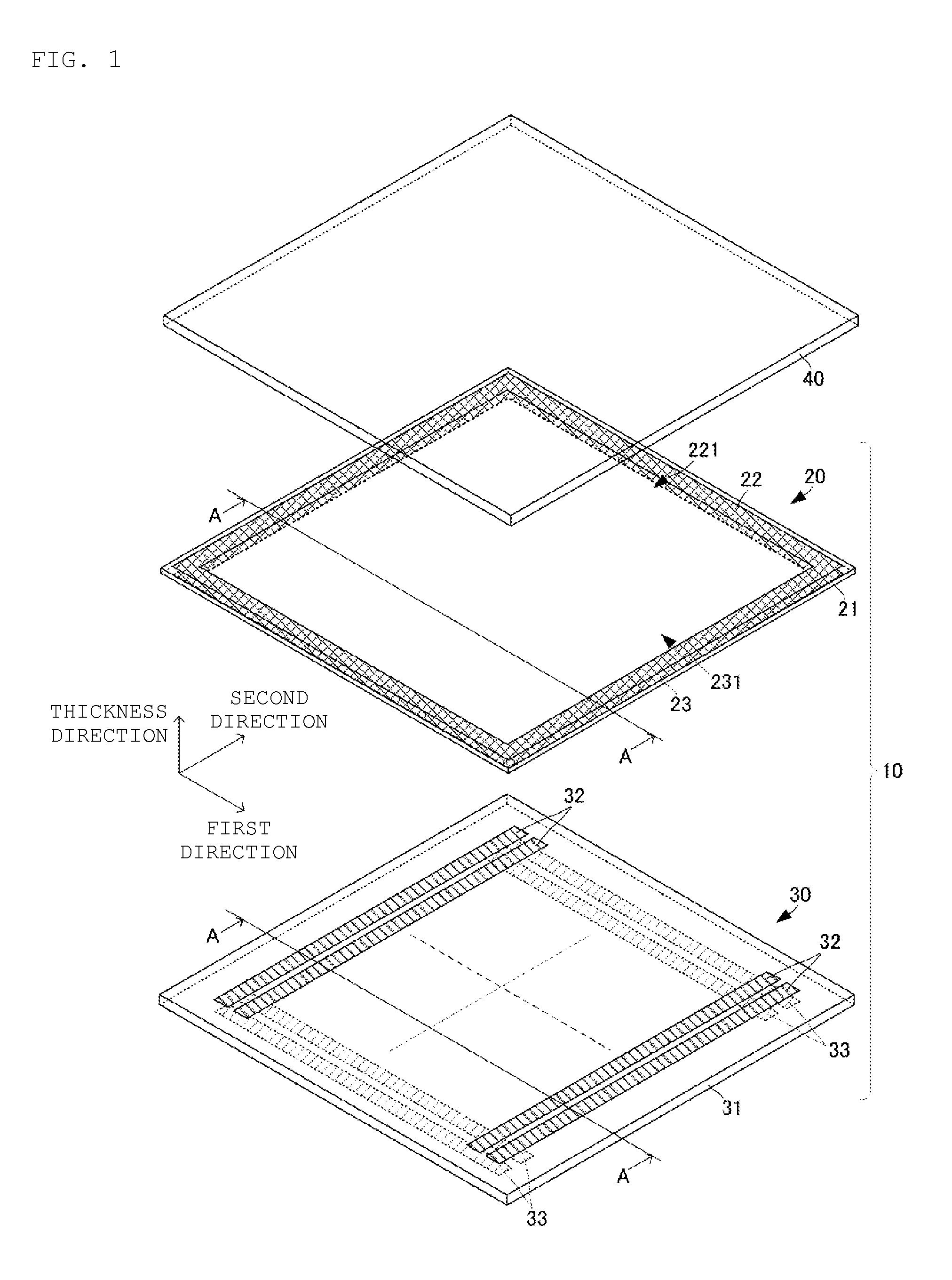
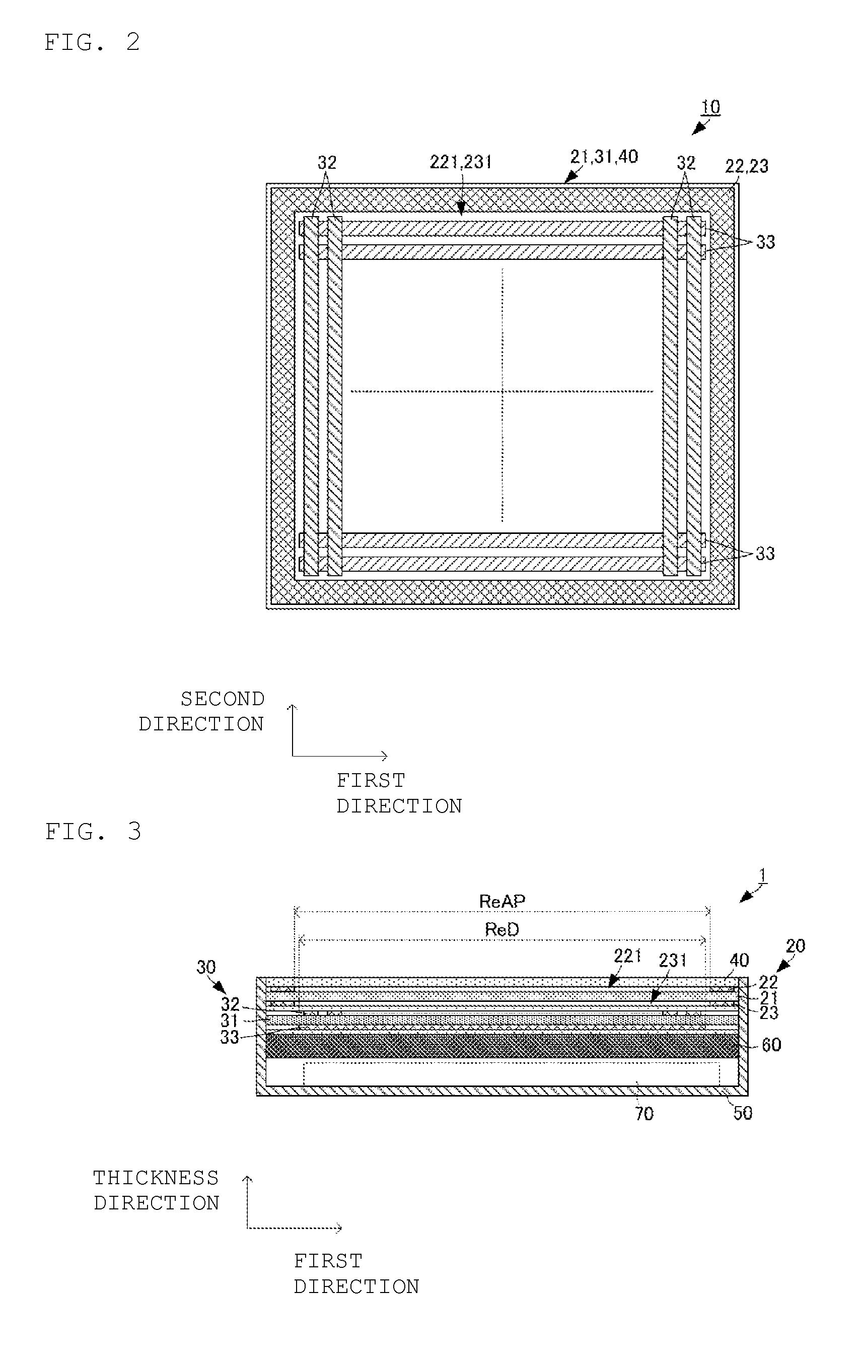
[0056]As described above, the touch sensor detecting the touch position and the pressing force with high sensitivity can be made using the configuration of the At this point, the touch sensor having the translucency can be made when the translucent material is used in the pressure detection sensor 20 (at least the piezoelectric film 21) and the position detection sensor 30. The use of the touch sensor having the translucency can display the display image of the display panel 60 on the operation surface without degrading the display image, even if the touch sensor is disposed between the display panel 60 and the operation surface as illustrated in FIG. 3. Particularly, in the case that a display image range of the display panel 60 is equal to the position detection region ReD of the position detection sensor 30, the pressure detection sensor 20 is constructed only with the piezoelectric film 21 in the position detection region ReD, so that the display image can more clearly be displ...

second embodiment

[0060]The pressure detection sensor 20A includes insulating films 220 and 230. The insulating films 220 and 230 have the translucency. The first piezoelectric detecting electrode 22 is formed in one of principal surfaces of the insulating film 220. The insulating film 220 is mounted on the first principal surface of the piezoelectric film 21 such that the first piezoelectric detecting electrode 22 abuts on the piezoelectric film 21. The second piezoelectric detecting electrode 23 is formed in one of principal surfaces of the insulating film 230. The insulating film 230 is mounted on the second principal surface of the piezoelectric film 21 such that the second piezoelectric detecting electrode 23 abuts on the piezoelectric film 21. In the configuration of the second embodiment, it is not necessary to form the first and second piezoelectric detecting electrodes 22 and 23 of the piezoelectric film 21, and the pressure detection sensor 20A can easily be formed.

[0061]The position detect...


PUM


Abstract

A touch sensor that includes a pressure detection sensor and a position detection sensor. The pressure detection sensor and the position detection sensor are sequentially disposed from an operation surface side of the touch sensor. The position detection sensor includes a dielectric substrate, first position detecting electrodes on a first principal surface of the dielectric substrate, and second position detecting electrodes on a second principal surface of the dielectric substrate. The pressure detection sensor includes a piezoelectric film, a first piezoelectric detecting electrode on a first principal surface of the piezoelectric film, and a second piezoelectric detecting electrode on a second principal surface of the piezoelectric film. The first and second piezoelectric detecting electrodes are disposed so as to not overlap the first and second position detecting electrodes.

Description

CROSS REFERENCE TO RELATED APPLICATIONS[0001]The present application is a continuation of International application No. PCT / JP2014 / 074039, filed Sep. 11, 2014, which claims priority to Japanese Patent Application No. 2013-195143, filed Sep. 20, 2013, the entire contents of each of which are incorporated herein by reference.FIELD OF THE INVENTION[0002]The present invention relates to a touch sensor that detects a touch position on an operation surface and detects push-in on the operation surface.BACKGROUND OF THE INVENTION[0003]Conventionally, there have been proposed various touch type input devices that detect operation input by an operator touching on an operation surface. Some touch type input devices detect a touch position in the operation surface and a pressure or a pressing amount of the operation surface.[0004]For example, a touch type input device disclosed in PTL 1 has a structure in which a flat pressure sensor (pressure detection sensor) and a flat electrostatic type pos...

Claims


Application Information

Patent Timeline
IPC IPC(8): G06F3/041G06F3/044
CPCG06F3/044G06F3/0414G06F2203/04105G06F3/0445G06F3/0446
Inventor ANDO, MASAMICHIKANO, HIDEKAZU
Owner MURATA MFG CO LTD
Learn More