
Detection device for side collision of vehicle and passenger protection system having the same

a technology for detection devices and passenger protection systems, which is applied in the direction of doors, pedestrian/occupant safety arrangements, instruments, etc., can solve the problems of increasing the space for arranging sensors, detection devices cannot clearly find the extent to which the reinforcing member is actually brought close to the interior of the vehicle compartment, and detection devices have the problem of detection

Inactive Publication Date: 2009-06-04
DENSO CORP +1
View PDF10 Cites 12 Cited by
  • Summary
  • Abstract
  • Description
  • Claims
  • Application Information

AI Technical Summary

Benefits of technology

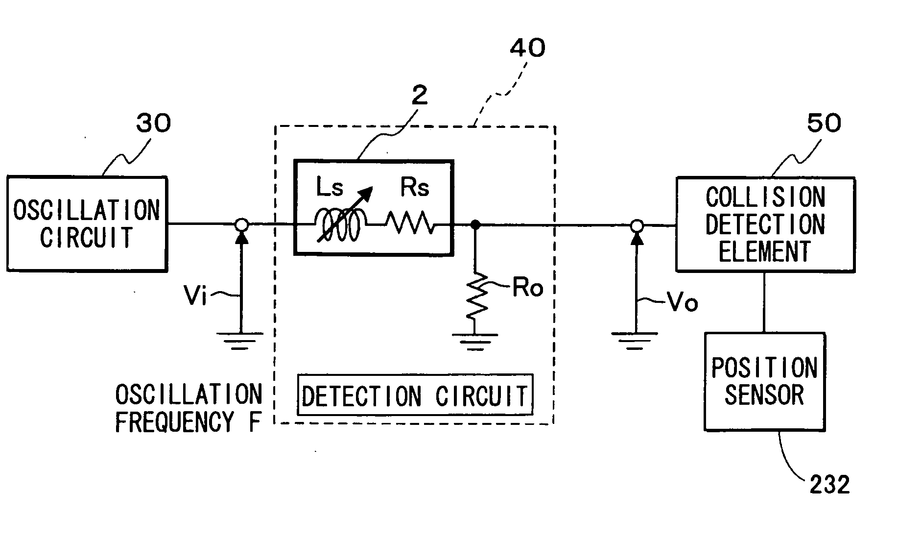
[0011]The present invention has been made in view of these circumstances. One object of the present invention is to provide such a detection device for side collision of a vehicle that can detect the degree of seriousness of collision. Alternatively, another object of the present invention is to provide such a detection device for side collision of a vehicle that can detect collision in a wide range and reduce a space for arranging the device and facilitate the arrangement of the device. Further, still another object of the present invention is to provide such a passenger protection system for a vehicle that uses the detection device for side collision of a vehicle. Still further, still another object of the present invention is to provide such a detection device for side collision of a vehicle that can detect collision in a wide range with high accuracy. Still further, still another object of the present invention is to provide such a detection device for side collision of a vehicle that can detect side collision without arranging a sensor in the interior of a side door.

Problems solved by technology

However, although the detection device for side collision of a vehicle described in the patent document 1 can detect whether or not the reinforcing member is deformed, the detection device cannot clearly find the extent to which the reinforcing member is actually brought close to the interior of the vehicle compartment by the deformation of the reinforcing member.
Thus, the detection device has the problem of detecting only collision at a specified position.
If it is intended to make a detection device detect collision in a wide range, a very large number of sensors need to be fixed to the reinforcing member, which causes the problem of increasing a space for arranging the sensors and the problem of complicating the arrangement of the sensors.
Thus, it is difficult to arrange the detection sensor in a range in which the door glass and the stay are moved up and down according to the method described in the patent document 1.
When the detection sensor is arranged at a position in which the detection sensor does not interfere in terms of space with the stay, a position in which the detection sensor is arranged is limited to positions in the front direction and in the rear direction of the vehicle of the side door, which presents the problem of making it difficult to detect collision in a wide range in the front and rear direction of the vehicle of the side door.
Further, the above-mentioned detection device for side collision of a vehicle detects collision only when the position of the reinforcing member having the sensor arranged thereon is displaced, so that the range of detection of the collision becomes very narrow.
Thus, there is presented a problem that the detection device can detect only collision at a specified position.
However, the conventional detection device for side collision of a vehicle employs a complex mechanical construction having two cantilever beams, so that the conventional detection device becomes very large in size, which presents a problem in the space for arranging the detection device.

Method used


Image

  • Detection device for side collision of vehicle and passenger protection system having the same
  • Detection device for side collision of vehicle and passenger protection system having the same
  • Detection device for side collision of vehicle and passenger protection system having the same

Examples


first embodiment

Modified Mode of First Embodiment

[0108]In the first embodiment, when the amplitude V1 becomes smaller than the amplitude threshold value Vth or when the absolute value of the quantity of a variation per unit time (time differential value) of the amplitude V1 exceeds the amplitude time variation threshold value Ath, the collision determination section 50 determines that an object collides with the outer plate 11 to deform the reinforcing member 13. In addition, the collision determination section 50 may detect collision when only one of both conditions is satisfied. That is, the collision determination section 50 determines that an object collides with the outer plate 11 to deform the reinforcing member 13 only when the amplitude V1 becomes smaller than the amplitude threshold value Vth. Further, the collision determination section 50 may determine that an object collides with the outer plate 11 to deform the reinforcing member 13 only when the absolute value of the quantity of a var...

second embodiment

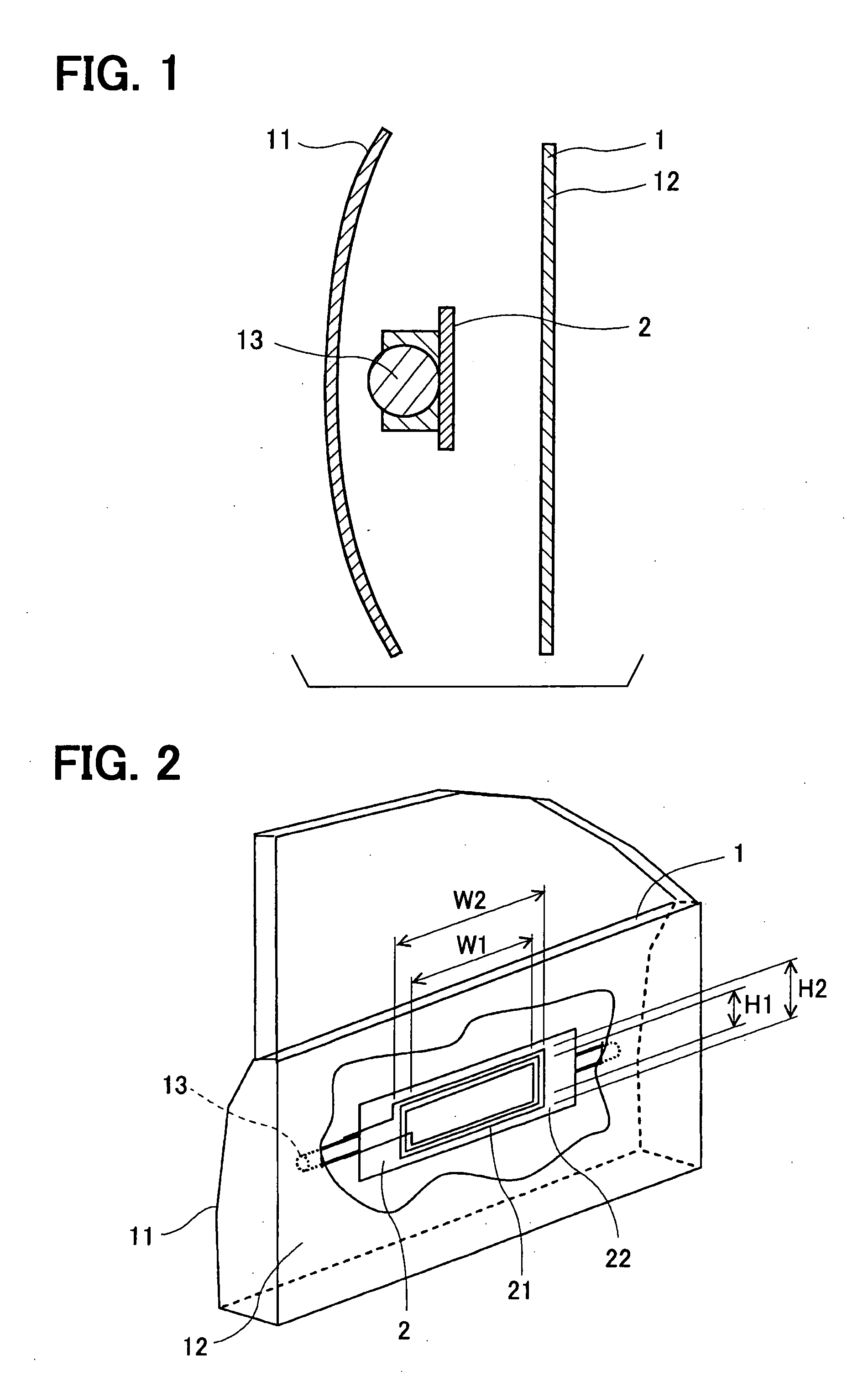
[0113]A detection device for side collision of a vehicle of a second embodiment will be described with reference to FIG. 9. The second embodiment is a mode in which the planar coil 21 is fixed to the reinforcing member 13 via a planar auxiliary plate 100 of a shielding member and in which a variation in the separate distance between the planar coil 21 and the inner plate 12 is detected.

[0114]FIG. 9 is a section view when the side door 1 is cut vertically to the left and right direction of the vehicle. In the first embodiment, the coil member 2 is fixed directly to the reinforcing member 13, but in second embodiment, the coil member 2 is fixed to the planar auxiliary plate 100. Here, the planar auxiliary plate 100 is formed of a rectangular plate made of metal such as iron or a ferromagnetic material. Alternatively, the planar auxiliary plate 100 may be formed of a resin film containing metal powder or a plastic plate coated with metal powder. The planar auxiliary plate 100 is fixed ...

third embodiment

Modified Mode of Third Embodiment

[0124]As a modified mode of the third embodiment, irrespective of whether or not the inner plate 12 has a through hole formed therein, even if the inner plate 12 is made of a non-magnetic material such as a resin module, by fixing the inside plate-shaped member 110 to the inner plate 12, a variation in the inductance Ls of the planar coil 21, that is, a variation in the quantity of magnetic flux interlinking the planar coil 21 can be surely detected. When the inner plate 12 is a resin module, the inductance Ls of the planar coil 21, that is, the quantity of magnetic flux interlinking the planar coil 21 is not varied according to the separate distance between the planar coil 21 and the inner plate 12. In this case, when the inside plate-shaped member 110 made of metal or a ferromagnetic material is used, the side collision can be surely detected.

[0125]In this regard, a distinctive portion in the second embodiment or its modified mode can be also appli...


PUM


Abstract

A detection device for side collision of a vehicle includes: an outer plate of a vehicle side door; an inner plate of the side door arranged separately from the outer plate; a reinforcing member arranged between the outer plate and the inner plate and having a bending rigidity higher than a bending rigidity of the outer plate; a detection subject member provided by at least one of the inner plate and a member fixed to the inner plate; a sensor detecting a separate distance between the detection subject member and the reinforcing member; and a determination element determining that the vehicle collides with an object based on an output value of the sensor.

Description

CROSS REFERENCE TO RELATED APPLICATIONS[0001]This application is based on Japanese Patent Applications No. 2007-289204 filed on Nov. 7, 2007, No. 2007-303042 filed on Nov. 22, 2007, No. 2007-309314 filed on Nov. 29, 2007, No. 2008-33547 filed on Feb. 14, 2008, and No. 2008-98519 filed on Apr. 4, 2008, the disclosures of which are incorporated herein by reference.FIELD OF THE INVENTION[0002]The present invention relates to a detection device for side collision of a vehicle that detects that an object has collided with a side door and a passenger protection system using the same.BACKGROUND OF THE INVENTION[0003]As a conventional detection device for side collision of a vehicle is proposed a detection device disclosed in, for example, JP-A-H05-93735 (patent document 1, which corresponds to U.S. Pat. No. 5,281,820). When the detection device for side collision of a vehicle, which is disclosed in the patent document 1, detects the deformation of a reinforcing member arranged in the inter...

Claims


Application Information

Patent Timeline
Patent Type & Authority Applications(United States)
IPC IPC(8): B60R21/0136
CPCB60J5/0441B60J5/0443G01B7/14B60R2021/0006B60R21/0136
Inventor KAWAURA, MASANORISANMA, NORIONONAKA, TOSHIHITO
Owner DENSO CORP
Learn More