[0081]According to the invention having the aforesaid configuration (1) or (2), when there is the deviation ±ΔRon with respect to the average value Ron of the on-resistance of the first semiconductor element (T1), the variance of the overcurrent detection value due to the presence of the deviation ±ΔRon is corrected in a manner that the change value ΔI1 caused by the deviation ±ΔRon is generated and the change value ΔI1 is subtracted from or added to the current I1 flowing through the first resistor (R1). Thus, the circuit can be interrupted by detecting the overcurrent flowing into the load circuit with a high accuracy. As a result, since it is not necessary to set the
electric wire to have a large
diameter in view of the flowing of the overcurrent, the
diameter of the
electric wire used for the load circuit can be made small.
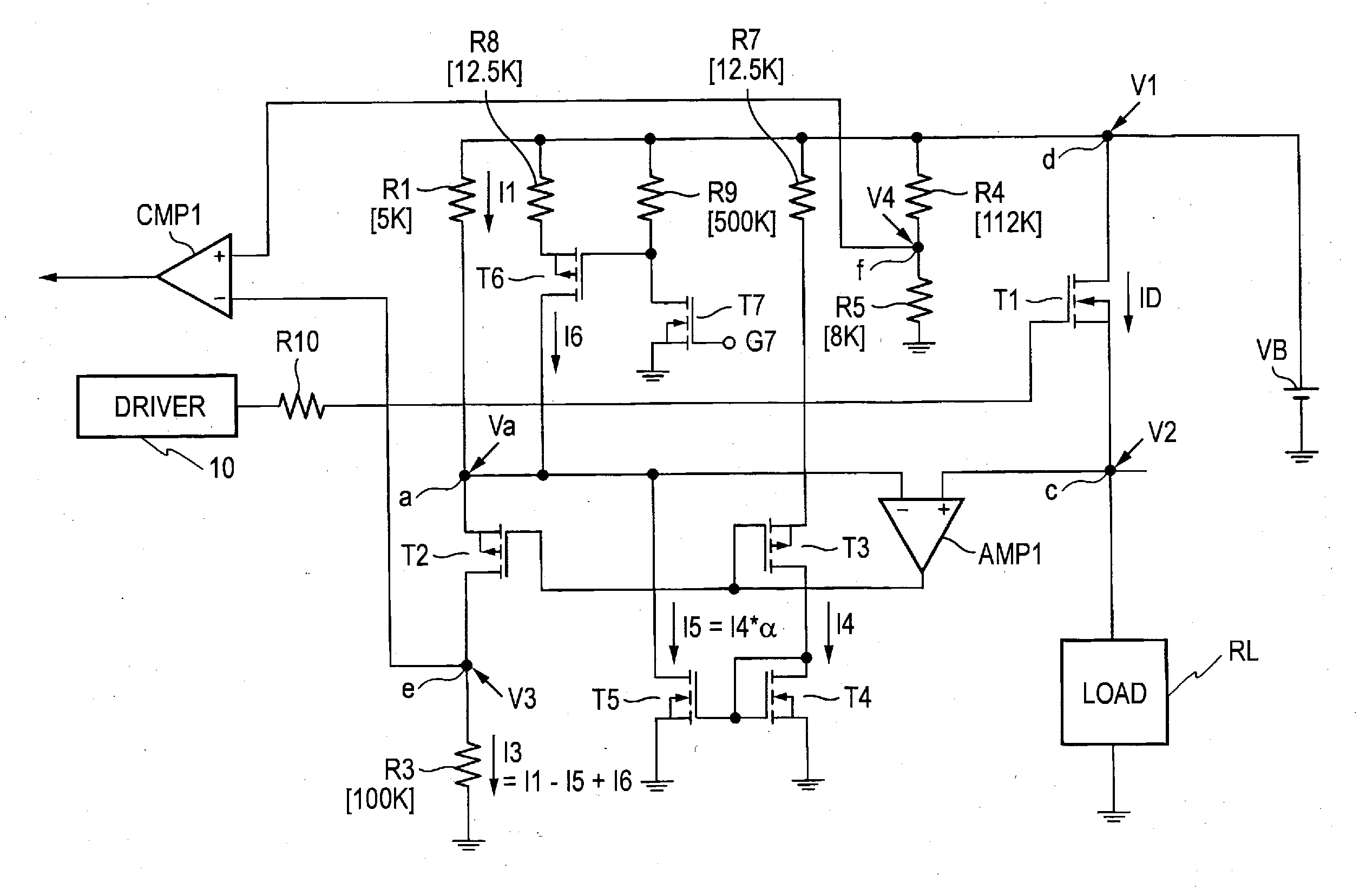
[0082]According to the invention having the aforesaid configuration (3) or (4), when the deviation ±ΔRon has a positive value, the current I4 proportional to the load current ID is generated, then the current I5 corresponding to the change amount ΔI1 is generated by using the current I4 and the current I5 is subtracted from the current I1. On the other hand, when the deviation ±ΔRon has a negative value, the current I1+I6 is generated by flowing the current I6 through the eighth resistor (R8) and further the current I5 is subtracted therefrom to thereby substantially add the change amount ΔI1 to the current I1. Thus, the current can be controlled with a high accuracy.
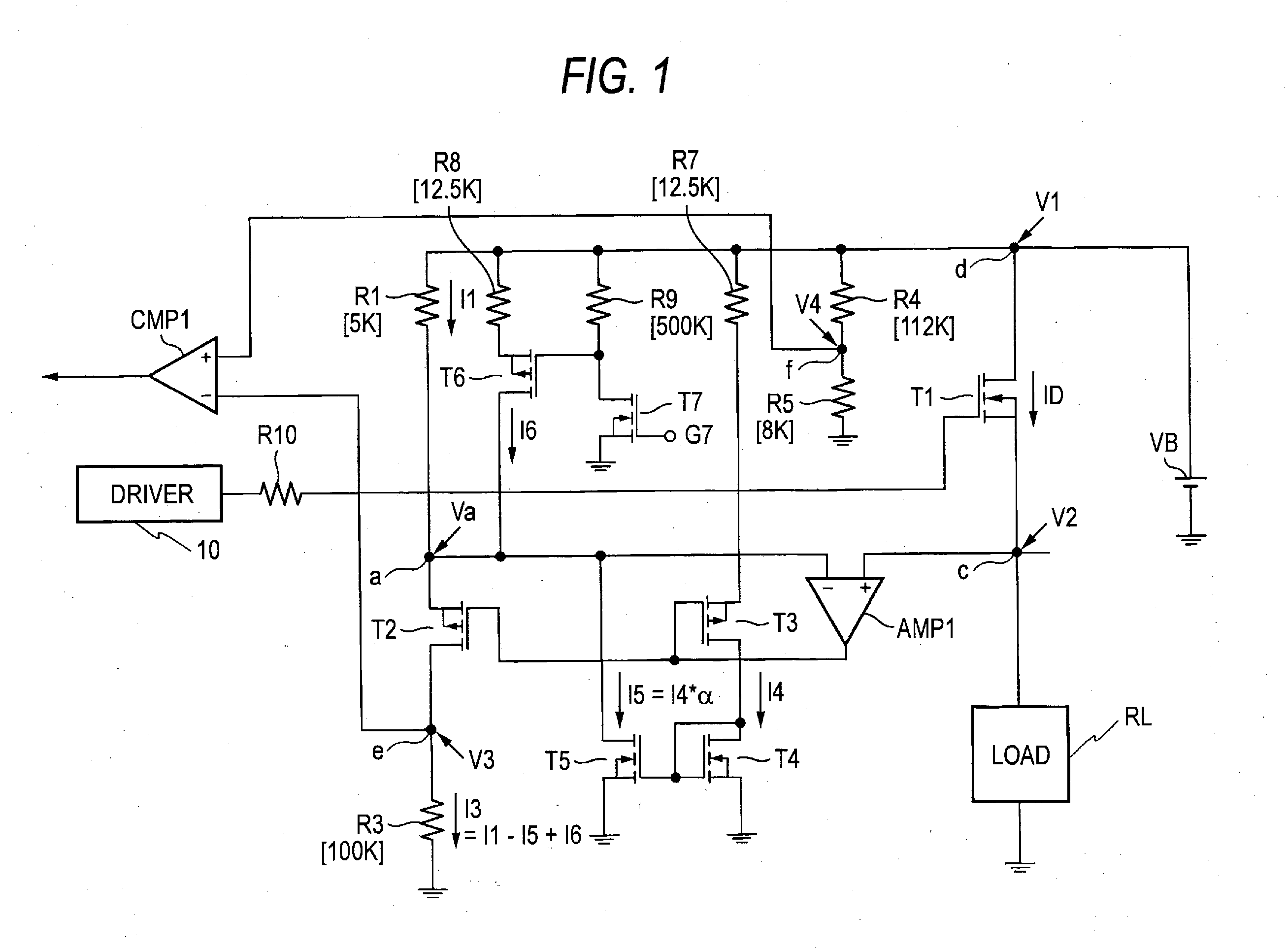
[0083]According to the invention having the aforesaid configuration (5) or (6), the determination
voltage V4 generated at the
coupling point between the fourth resistor (R4) and the fifth resistor (R5) is changed by setting the current flowing through the fifth resistor (R5) to be variable. Thus, when it is necessary to change the determination
voltage V4 due to the change of the on-resistance of the semiconductor element (T1), the determination voltage V4 can be changed to a desired value by adjusting the current flowing through the resistor R5. In other words, when the on-resistance of the semiconductor element (T1) changes toward small values, the current I10 is withdrawn from the point f to reduce the current flowing through the fifth resistor (R5), whereby the determination voltage V4 can be reduced. In contrast, when the on-resistance of the semiconductor element (T1) changes toward large values, the current I11−I10 is added to the point f to increase the current flowing through the fifth resistor (R5), whereby the determination voltage V4 can be increased. Thus, the overcurrent flowing into the load can be detected with a high accuracy. Further, since the fourth resistor (R4) and the fifth resistor (R5) necessary for generating the determination voltage V4 can be incorporated into an IC, the
miniaturization and the cost reduction of the apparatus can be realized.
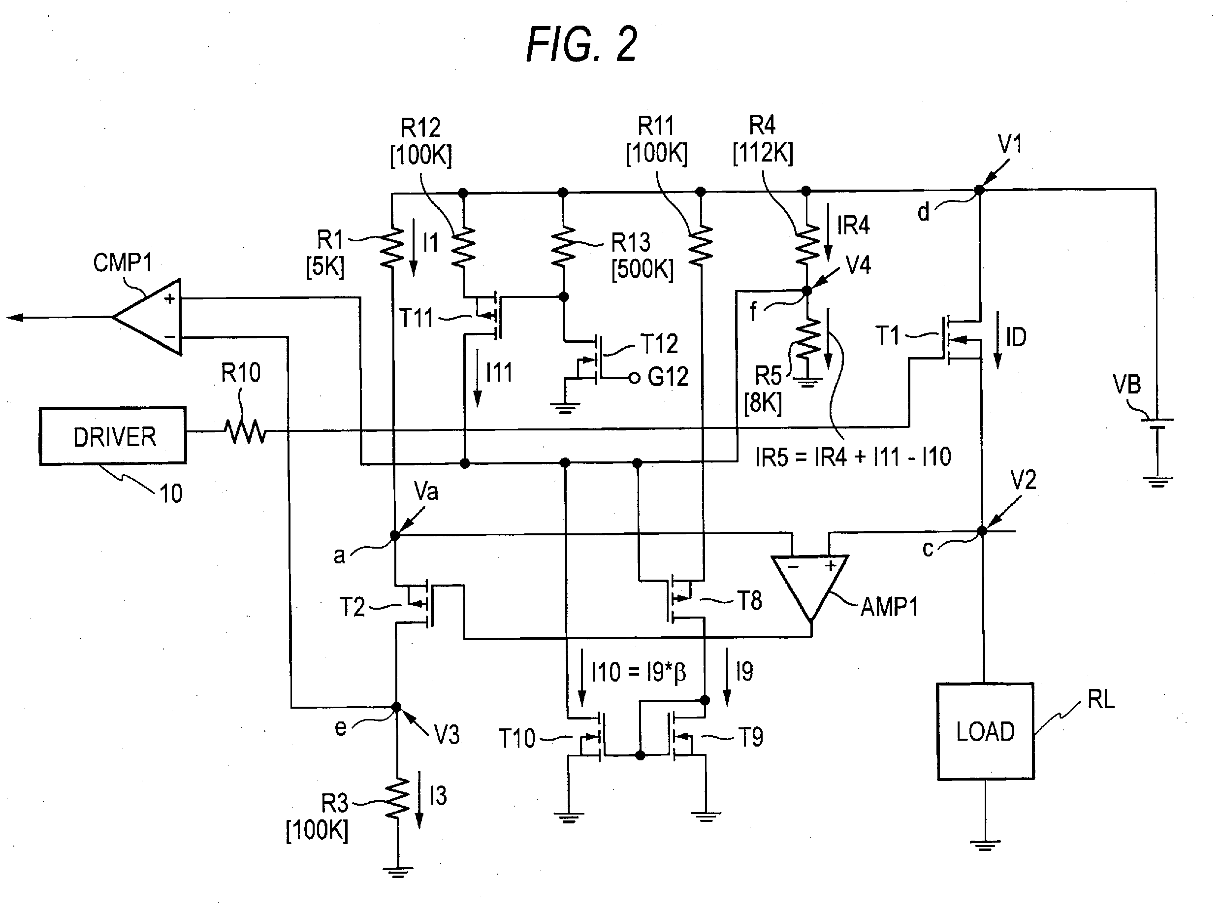
[0084]According to the invention having the aforesaid configuration (7) or (8), in the case where the on-resistance of the first semiconductor element is smaller than the average value (Ron), in order to generate the current I10 proportional to the deviation (ΔRon) at this time, the current I9 proportional to the load current ID is generated and the current I10 is generated by using the current I9. Then, the current I10 is subtracted from the current IR4 flowing through the fourth resistor (R4). On the other hand, in the case where the on-resistance of the first semiconductor element is larger than the average value (Ron), the current I11 is added to the current IR4 and the current I10 is subtracted therefrom, whereby substantially a desired current (I11−I10) is added to the current IR4. Thus, even when the on-resistance of the semiconductor element changes, the current control can be performed with a high accuracy.
[0085]According to the invention having the aforesaid configuration (9), the circuit which detects the voltage between the first main
electrode and the second main
electrode of the first semiconductor element (T1), the circuit which generates the determination voltage, and the
comparator (CMP1) which compares the voltage between the first main
electrode and the second main electrode of the first semiconductor element (T1) with the determination voltage are contained in the same
integrated circuit. Further, in a case where the output of the
comparator (CMP1) is not inverted when a current to be determined as an overcurrent is flown through the first semiconductor element (T1), the current flowing through the fourth resistor or the fifth resistor is adjusted so that the output of the
comparator (CMP1) is inverted. Thus, even in the case where the on-resistance Ron has a deviation, the overcurrent of the load circuit can be surely detected without being influenced by the deviation.

