Insert core and method for manufacturing a cylinder for internal combustion engine by making use of the insert core

Active Publication Date: 2005-05-31
KIORITZ
View PDF2 Cites 61 Cited by
  • Summary
  • Abstract
  • Description
  • Claims
  • Application Information

AI Technical Summary

Benefits of technology

[0015]The present invention has been made to overcome the aforementioned problems, and therefore an object of the present invention is to provide a method for manufacturing a cylinder for an internal combustion engine, which not only makes it possible to manufacture the cylinder by a die casting method such as a high-pressure die casting

Problems solved by technology

There is a problem however in the aforementioned method to cut out a scavenging port by mechanical means after the casting of raw cylinder body.
Namely, since the space for allowing a cutting tool to be inserted into a working portion is very narrow, it is very difficult to perform the mechanical working and to enhance the working accuracy of the scavenging port.
In this case however, since part of the insert core is left to remain in the cast product, the heat conductivity thereof is deteriorated and at the same time, various problems such as the deformation or peeling of the part of the insert core may occur.
However, even in the aforementioned manufacturing method, the following problems are raised.
In this case however, since the scavenging port-forming portion, the suction port-forming portion and the

Method used


Image

  • Insert core and method for manufacturing a cylinder for internal combustion engine by making use of the insert core
  • Insert core and method for manufacturing a cylinder for internal combustion engine by making use of the insert core
  • Insert core and method for manufacturing a cylinder for internal combustion engine by making use of the insert core

Examples


Example

[0043]The present invention will be further explained with reference to one embodiment of the manufacturing method of a cylinder for an internal combustion engine where an insert core is employed according to the present invention.

[0044]The cylinder for an internal combustion engine, which can be manufactured by the method according to this embodiment, is a cylinder 1 for a small air-cooled two-stroke gasoline engine as shown in FIG. 15 (a longitudinal sectional view wherein the scavenging duct thereof is longitudinally sectioned) and FIG. 16 (a longitudinal sectional view wherein the suction port and exhaust port thereof are longitudinally sectioned), which can be employed in a portable working machine. This cylinder 1 is formed of an aluminum alloy and comprises an integral body including a main body 2 having a cylinder bore 10 for allowing a piston 60 to be fitted therein, a head portion 3 provided therein with a squish dome-shaped combustion chamber 4, and a large number of cool...


PUM


Abstract

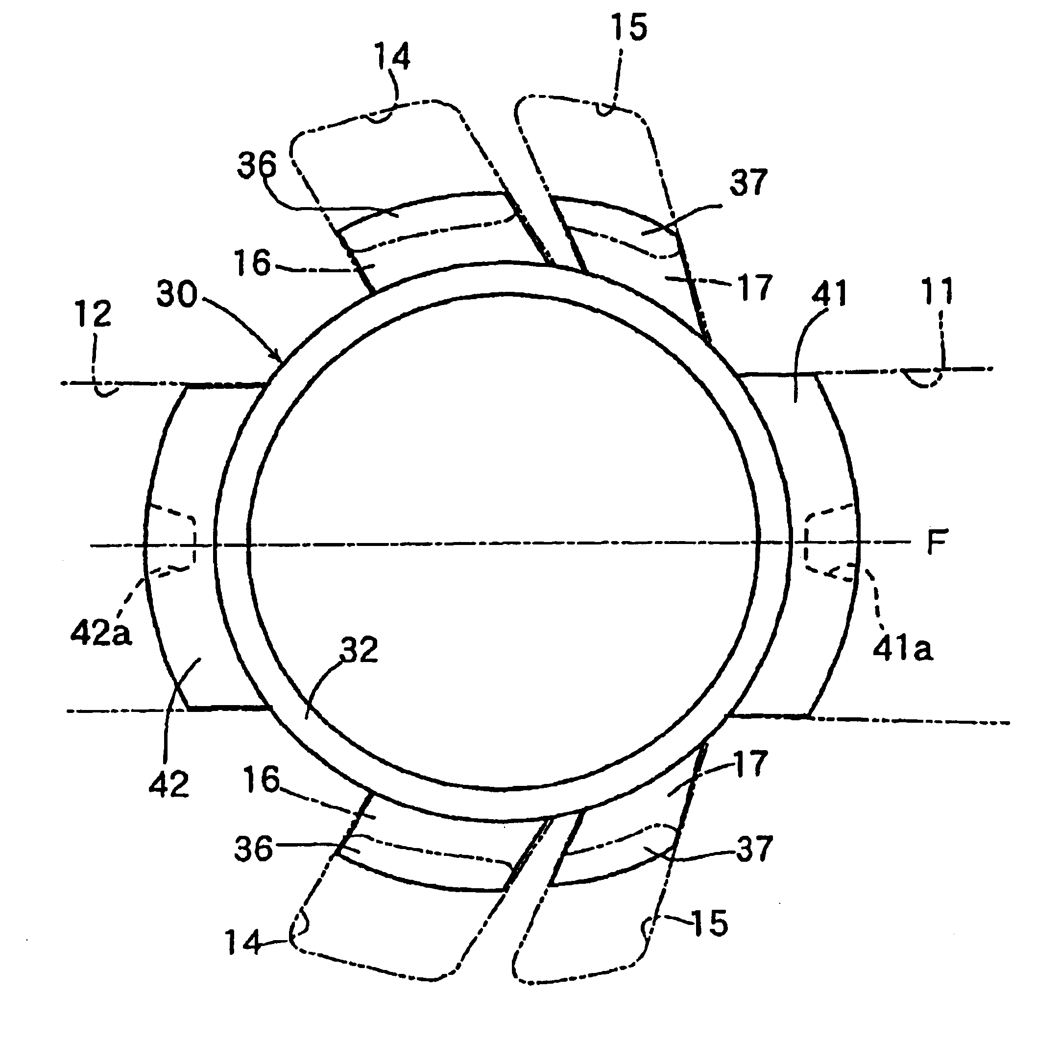
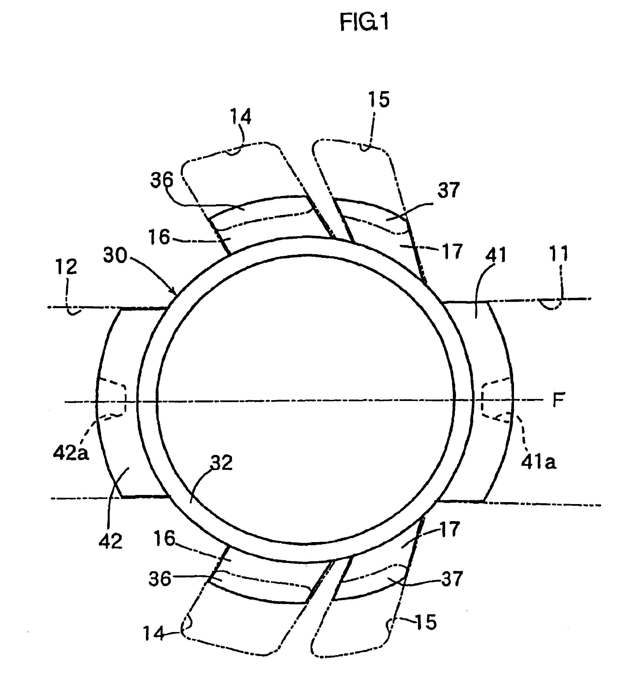
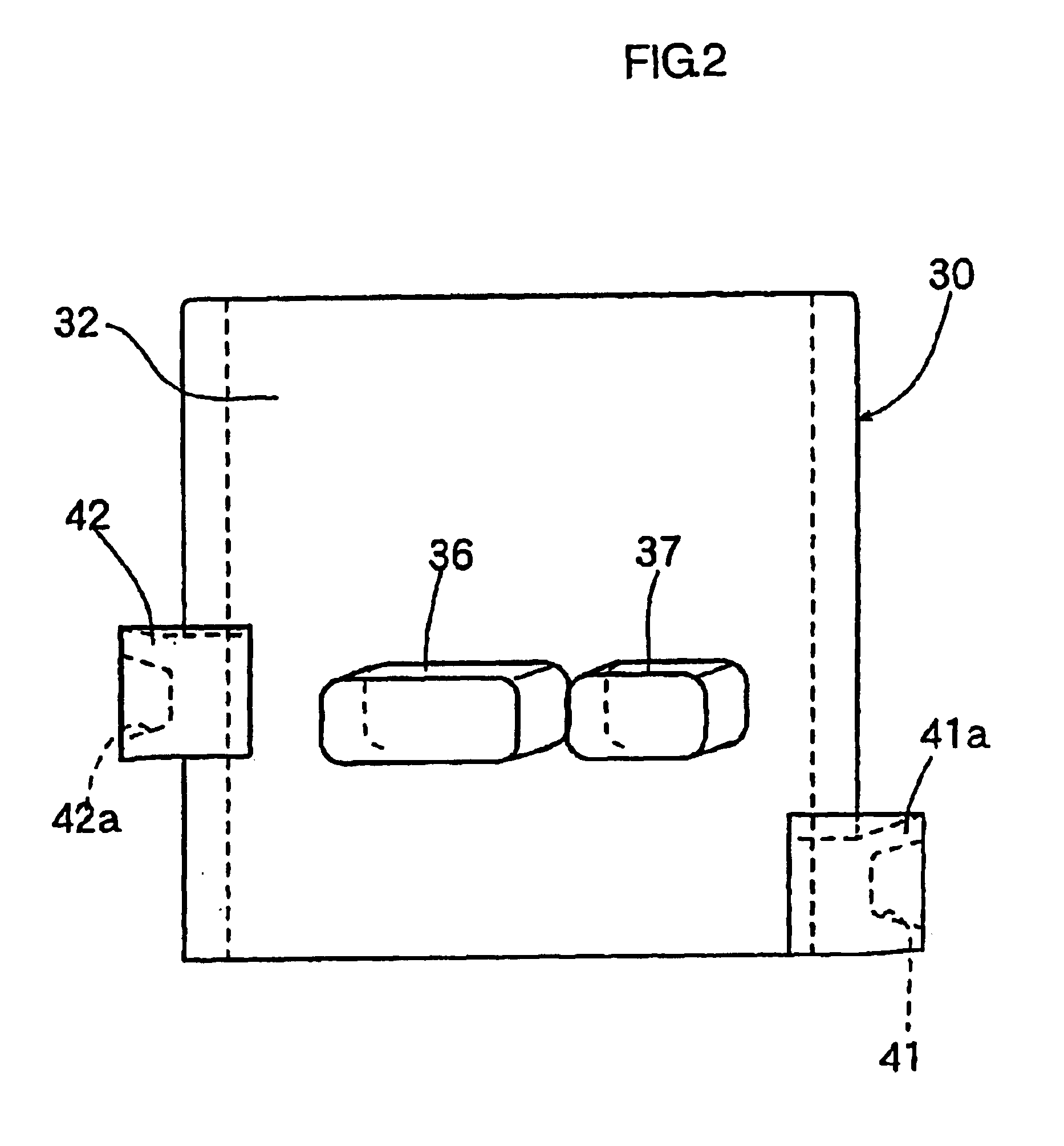
There is provided a method for manufacturing a cylinder for an internal combustion engine by making use of an insert core, which makes it possible to manufacture the cylinder by a die casting method such as a high-pressure die casting method at low cost and in high accuracy. The insert core to be employed herein includes: a cylindrical body having substantially the same outer diameter as the diameter of bore of the cylinder to be obtained; a scavenging port-forming portion projecting radially outward from the cylindrical body and having substantially the same cross-sectional configuration as that of the scavenging port; a suction port-forming portion projecting radially outward from the cylindrical body and having substantially the same cross-sectional configuration as that of at least the cylinder bore-side end portion of a suction port; and an exhaust port-forming portion projecting radially outward from the cylindrical body and having substantially the same cross-sectional configuration as that of at least the cylinder bore-side end portion of an exhaust port.

Description

BACKGROUND OF THE INVENTION[0001]1. Field of the Invention[0002]The present invention relates to an insert core to be employed in a method for manufacturing a cylinder for an internal combustion engine such as a small air-cooled two-stroke gasoline engine which is suited for use, for example, in a portable power working machine, and to a method of manufacturing the cylinder by making use of the insert core. In particular, the present invention relates to a method of manufacturing the cylinder by making use of an insert core which enables an undercut portion of the cylinder such as a scavenging port to be rationally formed on the occasion of manufacturing the cylinder by a die casting method such as a high-pressure die casting method.[0003]2. Description of the Related Art[0004]The cylinder of a small air-cooled two-stroke gasoline engine to be used in a portable power working machine is, as seen for instance from JP Laid-open Patent Publication (Kokai) No. 58-155114 (1983), generall...

Claims


Application Information

Patent Timeline
IPC IPC(8): B22D17/24B22D15/00B22D15/02B22C9/10F02F1/00B22D17/00B22D17/22
CPCB22C9/10B22D17/24B22D15/02
Inventor MATUURA, FUJIHIROSHOJI, TAKIOYAMADA, DAIJU
Owner KIORITZ
Why Eureka
Try Eureka