Photographing system

Inactive Publication Date: 2007-03-22
OLYMPUS CORP
View PDF5 Cites 57 Cited by
  • Summary
  • Abstract
  • Description
  • Claims
  • Application Information

AI Technical Summary

Benefits of technology

[0010] In the present invention, the color image capturing portion captures a color image of the subject and the color information detecting portion detects color information of the subject. A position in a color image of the detected color information is obtained from the correspond

Problems solved by technology

Digital camera has a merit that an image of an affected area can be easily obtained and the image can be checked immediately after the image capturing but also has a problem that colors of a photographed image

Method used


Image

  • Photographing system
  • Photographing system
  • Photographing system

Examples


first embodiment

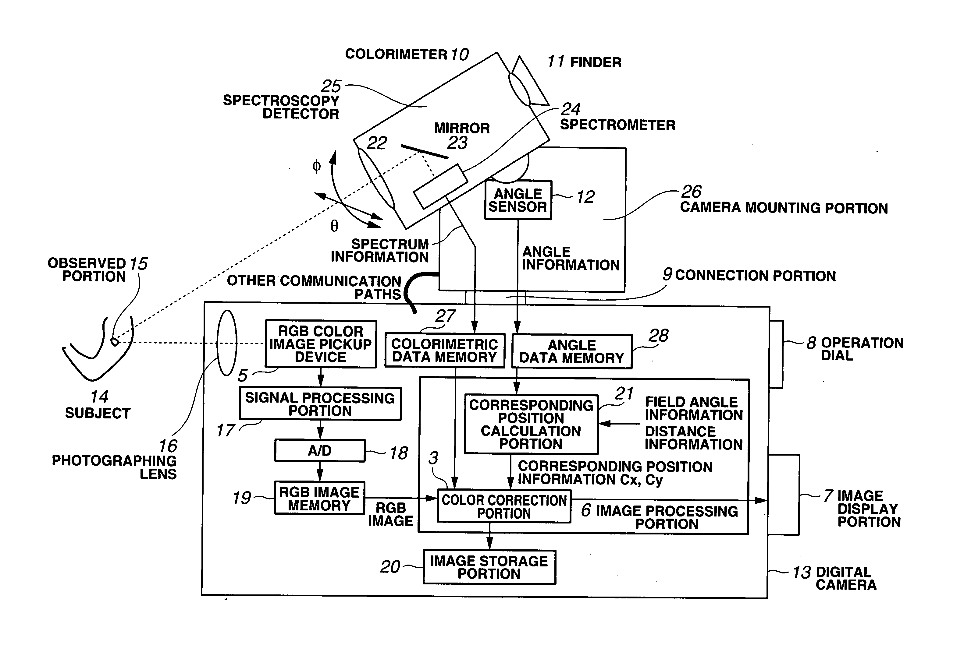
[0049] Embodiments of the present invention will be described below in detail referring to the attached drawings. FIG. 1 is a block diagram showing a photographing system according to the present invention.

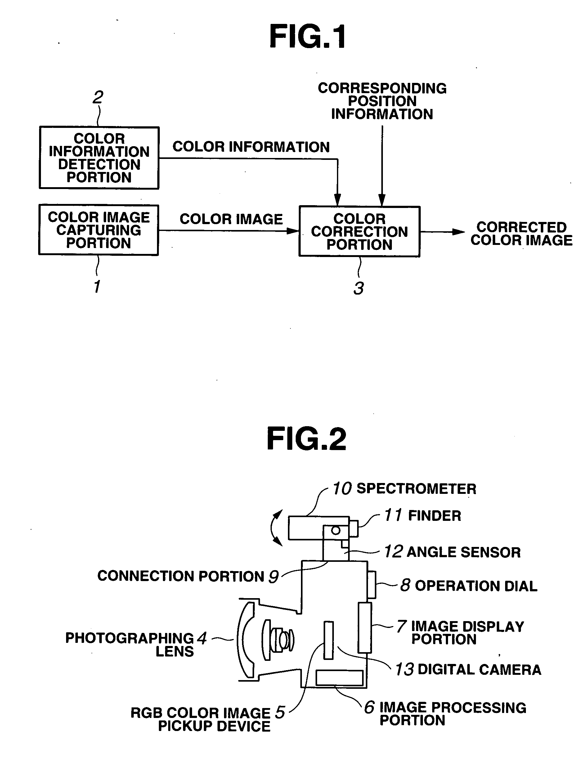
[0050] In FIG. 1, the photographing system has a color image capturing portion 1 and a color information detection portion 2. The color image capturing portion 1 comprises a digital camera or the like, for example, and captures an image of a subject, not shown, and outputs a color image of an RGB three-primary-color image or the like, for example, to a color correction portion 3.

[0051] The color information detection portion 2 detects color information at a predetermined position of a part of the subject photographed by the color image photographing portion 1 and outputs the detected color information to the color correction portion 3. To the color correction portion 3, a corresponding position information on a position in the color image from the color image photographing portio...

second embodiment

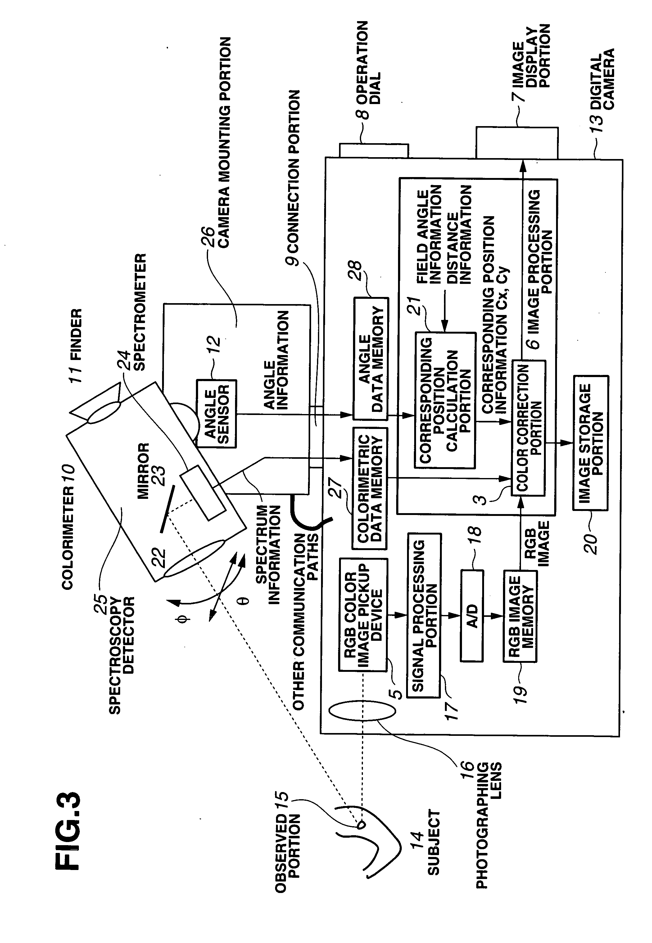
[0073]FIG. 11 relates to the present invention and is a block diagram showing a specific configuration of a digital camera 13′ and the spectrometer 10. In FIG. 11, the same reference numerals are given to the same components as those in FIG. 3 and the description will be omitted.

[0074] In the first embodiment, the calorimeter is moved vertically and horizontally and the angles θ, ø are detected so as to detect the corresponding position with the RGB image, but in this embodiment, the photographing direction of the colorimeter is controlled to a position aimed at by the digital camera.

[0075] As shown in FIG. 11, this embodiment is different from the first embodiment and a corresponding angle calculation portion 40 and a rotary motor 41 are provided. The spectroscopy detection portion 25 is configured so that it can move only vertically with respect to the camera mounting portion 26′. In the digital camera 13′, the observed portion 15 is captured at the center of the image capturing ...

third embodiment

[0080]FIGS. 13 and 14 relate to the present invention, and FIG. 13 is an explanatory view showing an appearance of the device. This embodiment shows an example that a colorimeter and a digital camera are mounted to a tripod stand or the like to constitute them separately.

[0081] In FIG. 13, reference numeral 201 is a tripod stand to which both the colorimeter 10 and the digital camera 13″ can be mounted. The colorimeter 10 and the digital camera 13″ are connected to an image processing unit 202, respectively. The image processing unit 202 is a control device comprised by a personal computer or the like.

[0082]FIG. 14 is a block diagram showing a specific configuration of the image processing unit 202 in FIG. 13

[0083] In FIG. 14, reference numeral 204 denotes an external equipment controller and a controller such as a USB, RS-232C, for example. Reference numeral 205 is a data input I / F to which spectrum information is inputted from the calorimeter 10 and the RGB image data is inputted...


PUM


Abstract

A photographing system for photographing a subject comprises color information detecting section for detecting color information of the subject, color image capturing section for capturing a color image of the subject, and color correcting section for performing color correction of a color image captured by the color image capturing section from corresponding position information of the color information detecting section and the color image capturing section so as to enable highly accurate color correction.

Description

CROSS REFERENCE TO RELATED APPLICATION [0001] This application is a continuation application of PCT / JP2005 / 009643 filed on May 26, 2005 and claims benefit of Japanese Application No. 2004-156750 filed in Japan on May 26, 2004, the entire contents of which are incorporated herein by this reference.BACKGROUND OF THE INVENTION [0002] 1. Field of the Invention [0003] The present invention relates to a photographing system in which color correction of input images is made using spectroscopic information of a subject. [0004] 2. Description of the Related Art [0005] Conventionally color management has been executed in many fields including industrial field, food field, medical field and the like. In the industrial field, for example, color management is carried out for the color of manufactured products, and calorimeters such as spectrometer, calorimeter are used to check if the product is finished in color within the standard. In the medical field, color management is performed for color ...

Claims


Application Information

Patent Timeline
IPC IPC(8): H04N5/228G01J3/51G01J3/46G06T1/00H04N1/46H04N1/60H04N9/04H04N9/73
CPCH04N9/735H04N9/045G01J3/508G01J3/524H04N25/11H04N23/125H04N23/88
Inventor KOMIYA, YASUHIROWADA, TORUKONNO, OSAMUSATO, NOBUMASA
Owner OLYMPUS CORP
Why Eureka
Try Eureka