Image processing device, image processing method, and program

Active Publication Date: 2009-11-26
PANASONIC INTELLECTUAL PROPERTY CORP OF AMERICA
View PDF13 Cites 60 Cited by
  • Summary
  • Abstract
  • Description
  • Claims
  • Application Information

AI Technical Summary

Benefits of technology

[0014]According to such an image processing device comprising the stated constituent elements for solving the aforementioned problem, the region to be masked is specified in accordance with the motion vectors that have been respectively calculated from the pixel blocks. In picture data, pixel blocks of an object (e.g., a person) in a foreground of ten show motion vectors having different magnitudes and directions from their counterpart pixel blocks included in the previous frame. An edge image corresponding to these pixel blocks is specified as the region to be masked.
[0015]This way, masking is performed on a foreground that shows an object (e.g., a person) located at a near distance from an imaging apparatus. Consequently, operation processing of detecting a correction parameter is performed on, out of the whole picture data obtained by taking a picture frame, an area other than the foreground, i.e., a background showing the real-world background.
[0016]In many cases, a background intrinsically includes structures (e.g., tall buildings) that have edge component values indicating horizontality and perpendicularity. More specifically, architectural structures, such as tall buildings, are thought to be included in the background.
[0017]In the above manner, the operation processing of detecting the correction parameter is performed only on feature amounts obtained from the unmasked re

Problems solved by technology

Therefore, it is not always the case that the operator can hold the video camera steady in a horizontal orientation while taking a video and walking at the same time.
Furthermore, if the operator takes a video without looking into the viewfinder of the video camera, i.e., without watching the video that is actually being taken, then

Method used


Image

  • Image processing device, image processing method, and program
  • Image processing device, image processing method, and program
  • Image processing device, image processing method, and program

Examples


Example

Embodiment 1

[0095]As one of many possible embodiments of the present invention, the present embodiment allows detecting, from current frame picture data, a slant as a correction parameter, and performing image processing on the current frame picture in accordance with the correction parameter. One example of such image processing is a rotation transformation.

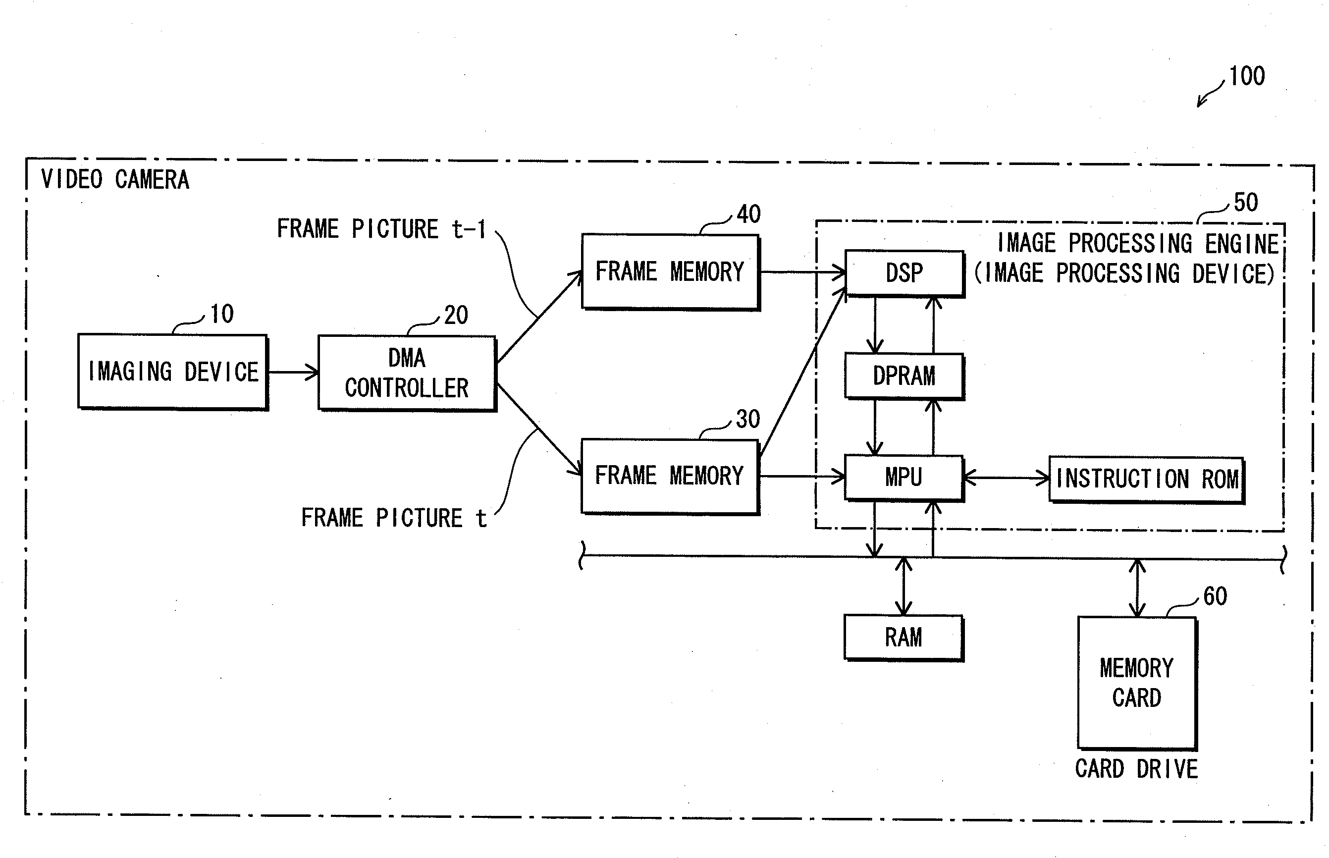
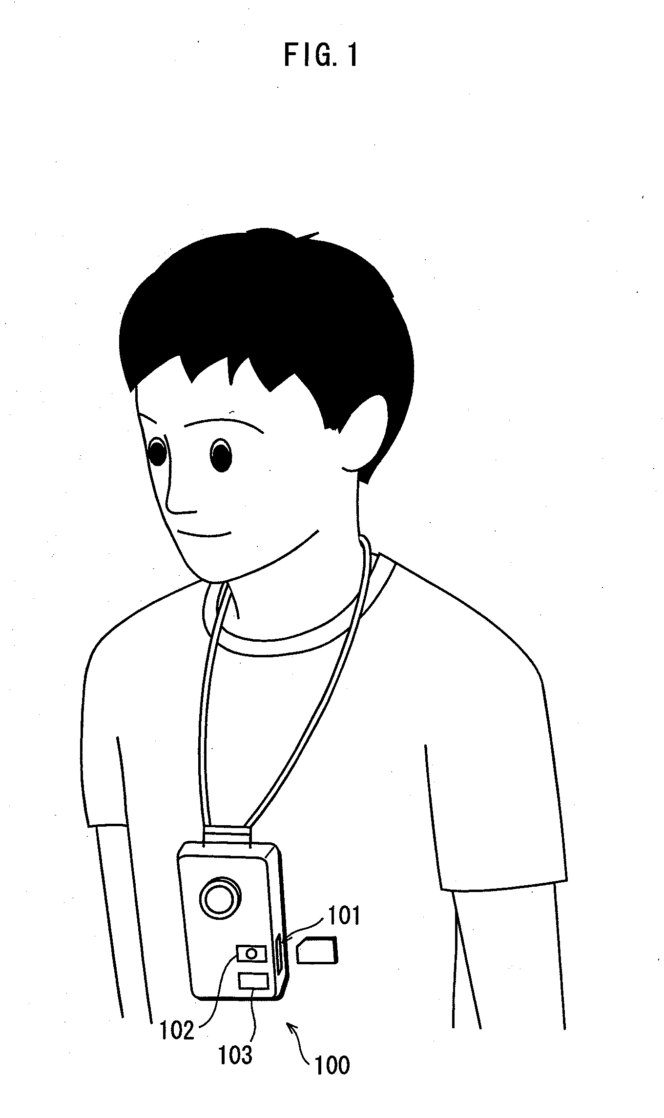
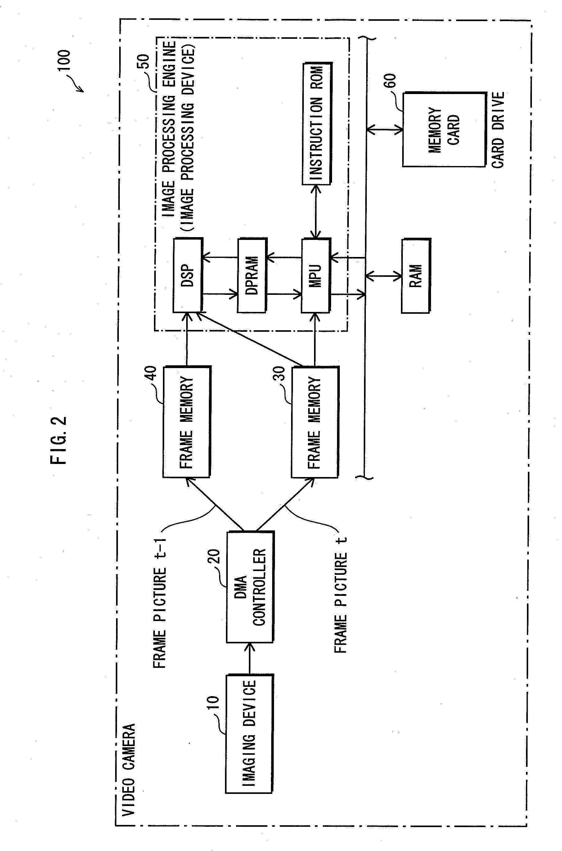
[0096]FIG. 1 shows a usage example of an imaging apparatus to which the image processing device of the present invention is applied. As shown in FIG. 1, a user uses a neck strap to wear a video camera 100 in which the image processing device of the present invention is provided, so that he can take a video by handling the video camera 100 in a hands-free manner. The casing of the video camera 100 has (i) a card slot through which a semiconductor memory card that would serve as a recording medium can be inserted / ejected, (ii) a record button 102 to receive an operation to start imaging processing, and (iii) a stop button 103 to r...

Example

Embodiment 2

[0169]FIG. 12 shows a hardware structure of an image processing device pertaining to Embodiment 2 of the present invention. Some constituent elements shown in FIG. 12 are configured the same as their counterparts in FIG. 11; these constituents elements are labeled the same reference numbers as their counterparts in FIG. 12, and the descriptions thereof are omitted.

[0170]As shown in FIG. 12, Embodiment 2 of the present invention is different from Embodiment 1 of the same in that (i) there is an additional constituent element, i.e., an inertial sensor 70 that can detect angular components associated with angles around a roll axis, and (ii) the line detection unit 2 utilizes an output from the sensor 70. Examples of such an inertial sensor 70, which can detect the angular components associated with the angles around the roll axis, include an acceleration sensor and a gyroscope.

[0171]The inertial sensor 70 obtains the slant angle around the roll axis which was measured at ti...

Example

Embodiment 3

[0177]The present embodiment relates to improvements made in a case where the coordinates in which a camera holder is positioned move. The coordinates in which the camera holder is positioned move when, for example, he / she is taking a picture from a moving vehicle, for example, a car. In such a case, there are times when the movement amounts that are calculated from an edge image showing architectural structures seem relatively large in the picture taken. Here, if the judgment of determining an edge image based on which the error correction should be performed is made in the same manner as Embodiment 1, i.e., merely in accordance with magnitudes of motion vectors, the edge image showing the architectural structures may be misjudged to be a foreground edge image. In this case, the slant angle cannot be obtained from feature amounts of the edge image showing the architectural structures, and accordingly, it is ineffective to use the above-described scheme of estimating the...


PUM


Abstract

A motion vector calculation unit 4 calculates inter-frame movement amounts. A masked region specification unit 5 separates the entire edge image of frame feature data into (i) an edge image showing relatively large movement amounts and (ii) an edge image showing relatively small movement amounts. The masked region specification unit 5 then specifies the edge image showing relatively large movement amounts as a region to be masked. This way, a correction parameter is detected from a region other than the masked region. When the correction parameter is a slang angle, a slant correction unit 7 performs slant correction on a frame picture obtained by an image sensor.

Description

TECHNICAL FIELD[0001]The present invention belongs to a technical field of image correction processing.BACKGROUND ART[0002]Image correction processing is technology to detect a correction parameter from frame picture data to be processed and to make corrections to the frame picture data in accordance with the correction parameter. Conventional image correction processing includes an image slant correction technique and an image stabilization technique.[0003]An image slant correction technique is a technique to estimate an angle of slant (hereafter, “slant angle”), by which the image is slanted with respect to a reference angle, and to correct the image in accordance with the slant angle. An image stabilization technique is a technique to correct shakes shown by frame picture data pieces of frame pictures by stabilizing backgrounds of the frame picture data pieces in the same position, the frame pictures being taken in succession, and the shakes being triggered when taking the frame ...

Claims


Application Information

Patent Timeline
IPC IPC(8): G06K9/40H04N5/225H04N5/232
CPCG06T7/0042G06T7/2006G06T2207/30196H04N5/23248H04N19/17H04N19/51H04N19/103H04N19/117H04N19/14H04N19/139G06T7/73G06T7/215H04N23/68
Inventor YAMADA, HITOSHI
Owner PANASONIC INTELLECTUAL PROPERTY CORP OF AMERICA
Why Eureka
Try Eureka