Touch panel and method for operating the same, and electronic apparatus and method for operating the same

Active Publication Date: 2010-02-04
SONY CORP
View PDF4 Cites 61 Cited by
  • Summary
  • Abstract
  • Description
  • Claims
  • Application Information

AI Technical Summary

Benefits of technology

[0025]According to the above-described embodiments of the present invention, pulses are applied in a selected order to n1 first line electrodes (n1 is an integer of at least 1 and not greater than n) selected from among n first line electrodes. For example, in a normal standby mode, pulses are applied only to a number smaller than n of the first line electrodes, to detect a double click operation, a slide operation, and a single click operation. Only in the case of detecting a specific operation, such as a drag ope

Problems solved by technology

As such, it is necessary to carry out the all line scan twice to recognize the double click oper

Method used


Image

  • Touch panel and method for operating the same, and electronic apparatus and method for operating the same
  • Touch panel and method for operating the same, and electronic apparatus and method for operating the same
  • Touch panel and method for operating the same, and electronic apparatus and method for operating the same

Examples


first embodiment

[0042]A capacitive type touch panel according to the present invention will now be described.

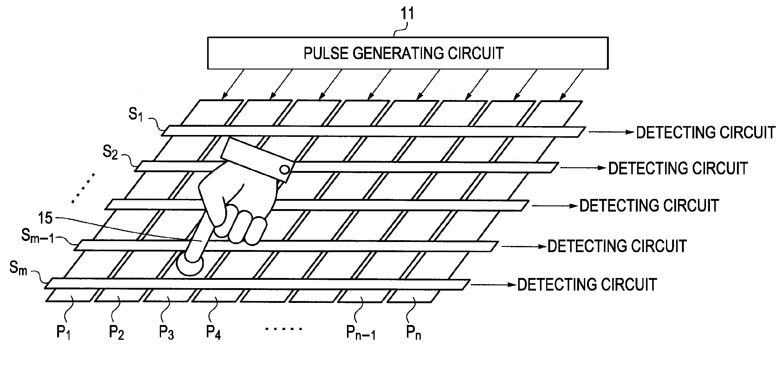
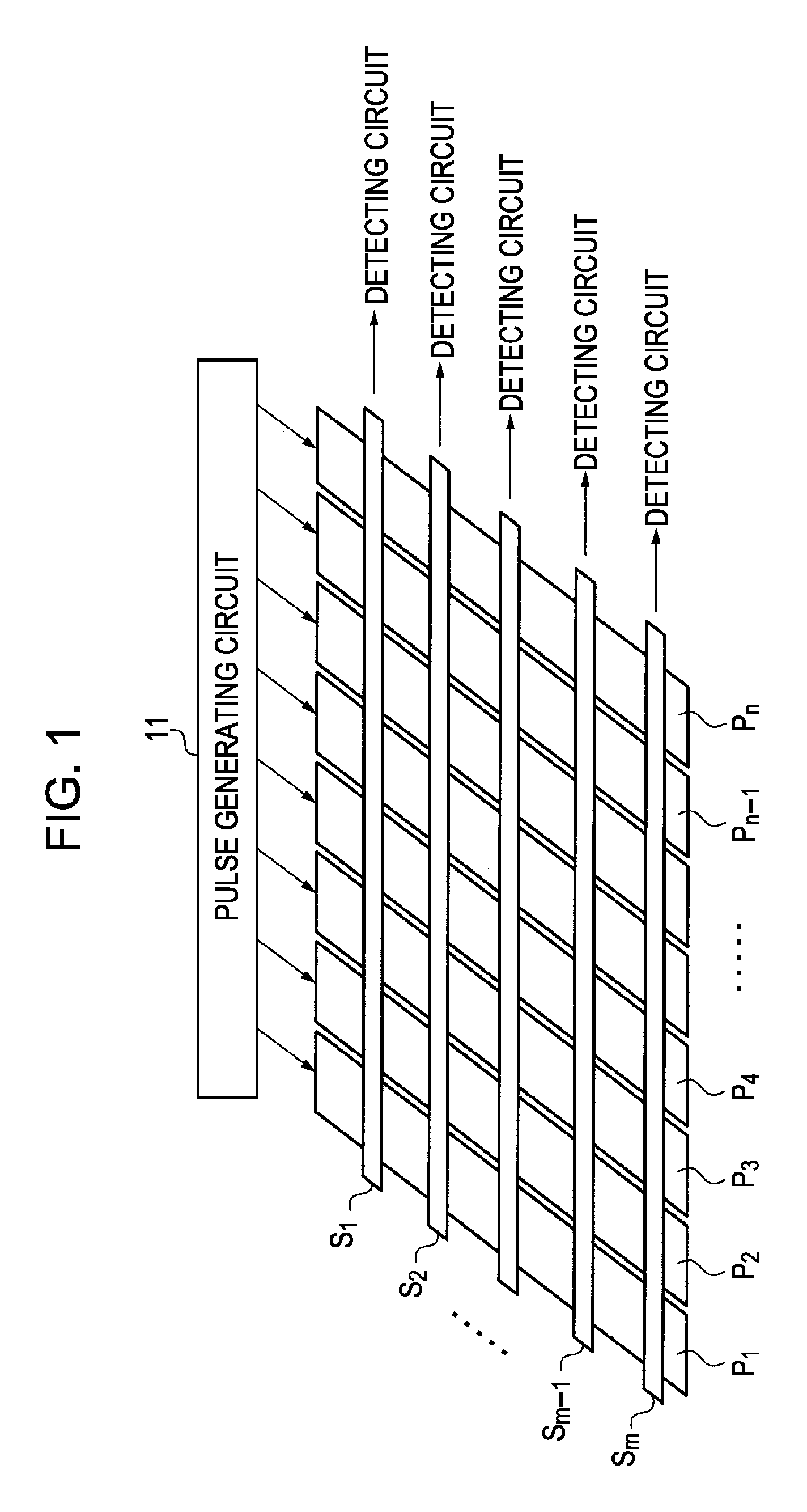
[0043]Referring to FIG. 1 which shows the touch panel of the first embodiment, the touch panel includes pulse lines P1 to Pn, which are constituted by n line electrodes (n is an integer of 2 or greater), and sense lines S1 to Sm, which are constituted by m line electrodes (m is an integer of 2 or greater). The pulse lines and the sense lines are insulated from each other and provided to orthogonally cross each other to form a matrix structure. In the present embodiment, the pulse lines P1 to Pn are arranged in parallel and at equal spacings. Here, the number n of the pulse lines P1 to Pn is an even number. Similarly, the sense lines S1 to Sm are arranged in parallel and at equal spacings. The number n, length, width, and spacing between the pulse lines P1 to Pn, as well as the number m, length, width, and spacing between the sense lines S1 to Sm may be determined as appropriate according to ...

second embodiment

[0068]A touch panel according to the present invention will now be described.

[0069]This touch panel is configured such that, during standby, pulses are applied to every certain ordinal number of lines among the pulse lines P1 to Pn. For example, in the example shown in FIG. 8A, pulses are applied to the pulse lines P2, P5, and P8. Otherwise, the touch panel of the second embodiment is identical to that of the first embodiment.

[0070]According to the second embodiment, effects similar to those in the first embodiment can be obtained.

third embodiment

[0071]A touch panel according to the present invention will now be described.

[0072]This touch panel is configured such that, during standby, a plurality of pulse lines among the pulse lines P1 to Pn are made into a group and pulses are applied to respective ones of such groups. For example, in the example shown in FIG. 8B, the pulse lines P2 and P3, the pulse lines P5 and P6, and the pulse lines P8 and P9 are made into groups, and the pulses are applied to the respective groups. Otherwise, the touch panel of the third embodiment is identical to that of the first embodiment.

[0073]According to the third embodiment, effects similar to those in the first embodiment can be obtained. In addition, as a plurality of pulse lines among the pulse lines P1 to Pn are made into a group and a pulse is applied to that group, effects comparable to those which would be obtained by a wider pulse line can be obtained. For example, a touch on the panel can be detected more easily.


PUM


Abstract

A touch panel includes n first line electrodes (n is an integer of 2 or greater) to which pulses are applied, m second line electrodes (m is an integer of 2 or greater) for use in detection, the second line electrodes being arranged to cross the first line electrodes, and a pulse generating circuit configured to apply pulses, in a selected order, to first line electrodes (n1 is an integer of at least 1 and not greater than n) selected from among the n first line electrodes. A touched position on the touch panel is detected by detecting a change in capacitance between one of the first line electrodes and one of the second line electrodes.

Description

BACKGROUND OF THE INVENTION[0001]1. Field of the Invention[0002]The present invention relates to a touch panel and a method for operating the touch panel, and an electronic apparatus and a method for operating the electronic apparatus. In particular, the present invention is suitably applied to electronic apparatuses having a touch panel as an input device.[0003]2. Description of the Related Art[0004]A touch panel, also called a touch screen, is an input device with which an operator operates an apparatus by touching the screen with a finger, which has been used in various electronic apparatuses.[0005]There are various types of touch panels, including a capacitive type, a resistive film type, an ultrasonic type, an infrared type, and an electromagnetic induction type. While touch panels of the resistive film type have been widely used before, touch panels of the capacitive type have only recently attracted attention and enable multi-point detection that would be difficult with touch...

Claims


Application Information

Patent Timeline
IPC IPC(8): G06F3/045
CPCG06F3/044G06F3/0446
Inventor KITAMURA, RYOTA
Owner SONY CORP
Why Eureka
Try Eureka