Reducing buffer overflow

a buffer overflow and buffer technology, applied in data switching networks, instruments, frequency-division multiplexes, etc., can solve the problems of buffer overflow, buffer overflow, buffer overflow, etc., to reduce buffer overflow or eliminate the effect of buffer overflow, saving buffer overflow, and small roundtrip tim

a buffer overflow and buffer technology, applied in data switching networks, instruments, frequency-division multiplexes, etc., can solve the problems of buffer overflow, buffer overflow, buffer overflow, etc., to reduce buffer overflow or eliminate the effect of buffer overflow, saving buffer overflow, and small roundtrip tim

US8170557B2Inactive Publication Date: 2012-05-01TELEFON AB LM ERICSSON (PUBL)

Image

  • Reducing buffer overflow
  • Reducing buffer overflow
  • Reducing buffer overflow

Examples


example calculation

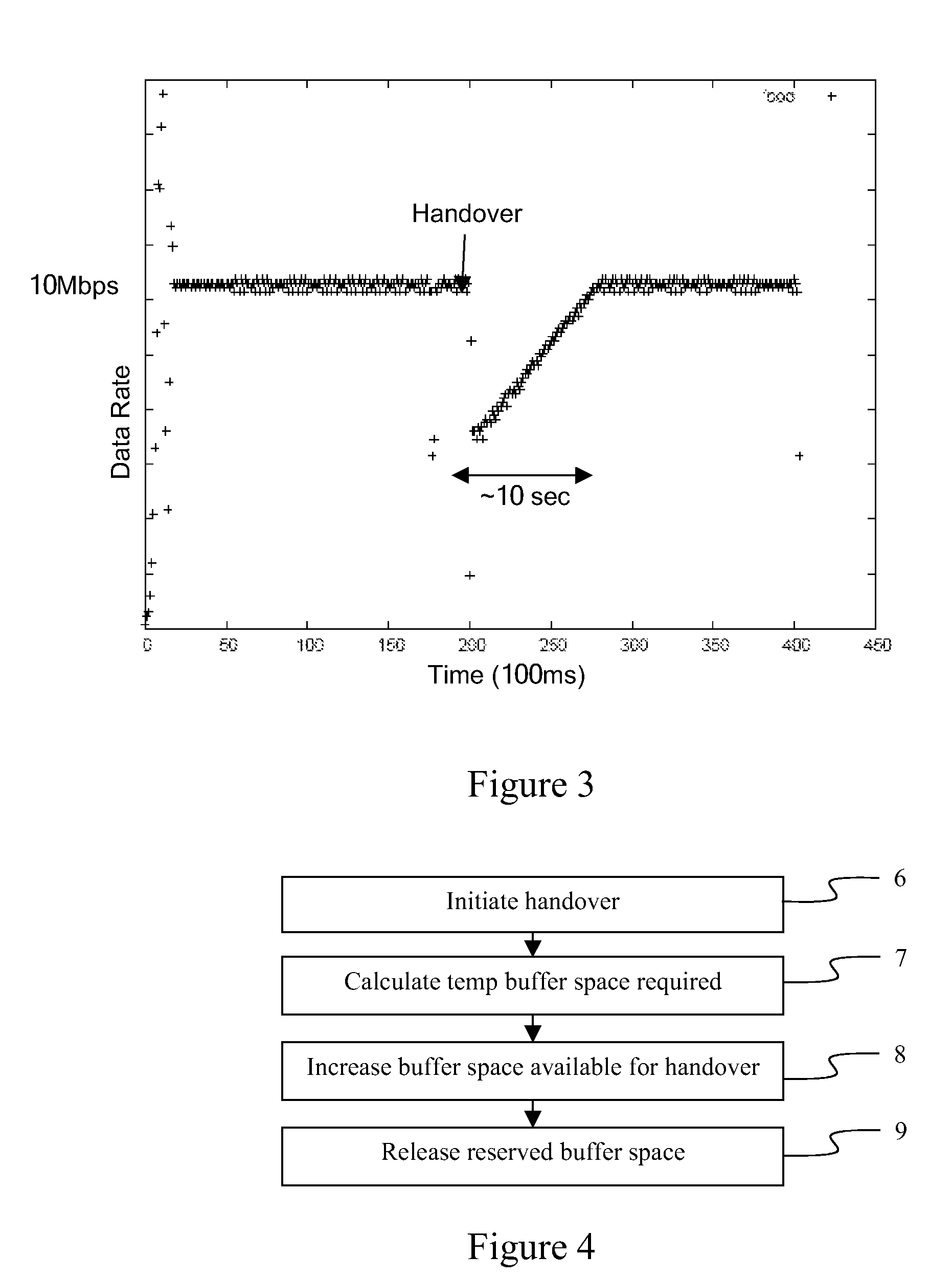
[0066]Assume the following network case:[0067]N=100 users in a cell[0068]Base round-trip time RTT=100 ms[0069]Handover interruption time 100 ms[0070]Handover frequency: F=1 / minute

[0071]The usual setting for downlink buffers is BDP or 2*BDP. This is to ensure that TCP can survive a single buffer drop event.

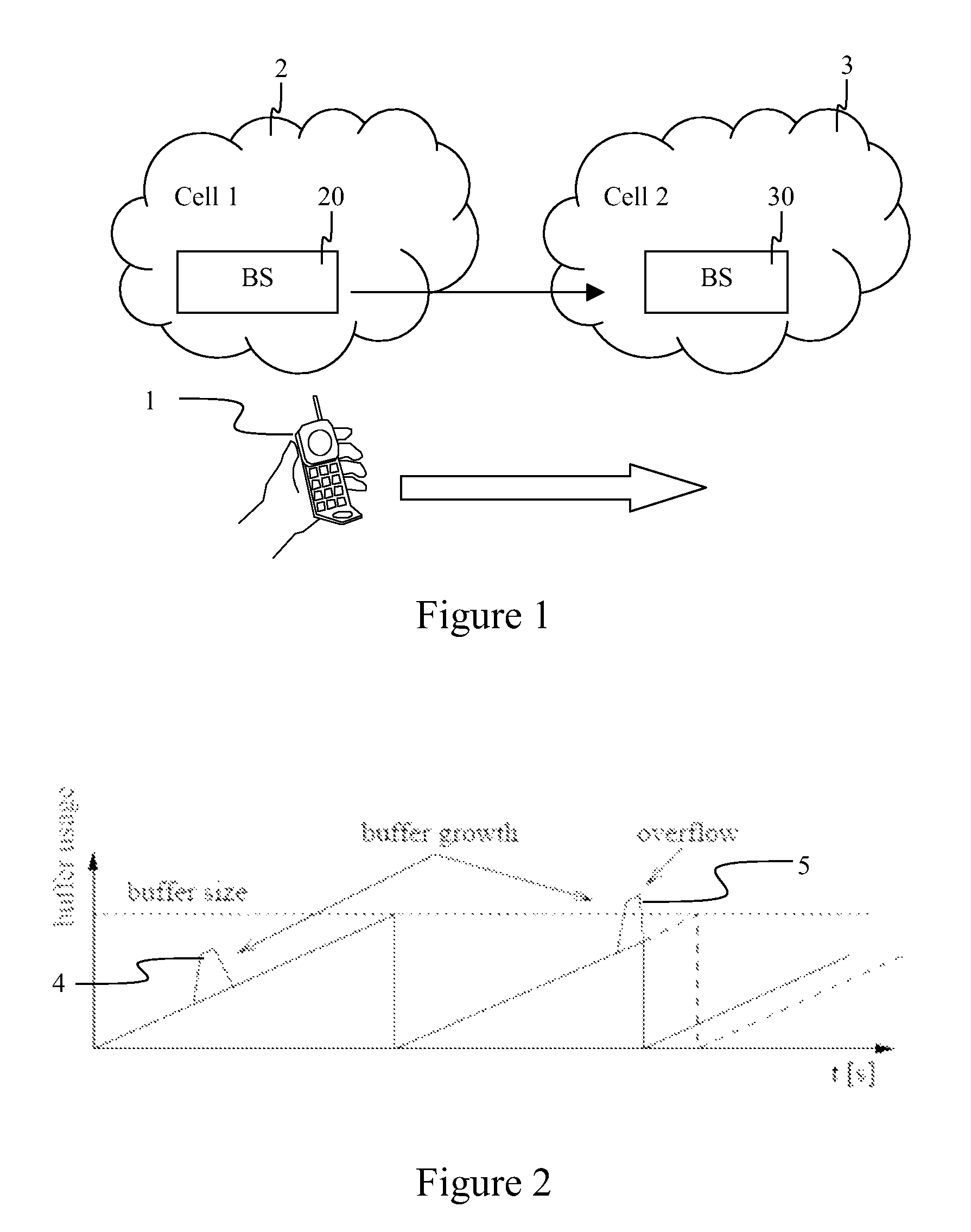
[0072]Assume that the buffer growth is Bgrowth=Rd*RTT. It means that if the buffer size is BDP, the probability of buffer overrun is Poverrun=100%. If the buffer size is 2BDP, then Poverrun is calculated according to equation 6:

[0073]Poverrun=2×BDP(2⁢BDP+BDP)=67⁢%(6)

[0074]By dynamically allocating temporary buffer space to each user when a handover is required, Poverrun is reduced to 0%.

[0075]If, instead of dynamically allocating temporary buffer space, a larger buffer was provided, in order to achieve a maximum overrun probability of Poverrun, a buffer size must be provided according to equation 7:

[0076]Bsize>BDP×(2-Poverrun)Poverrun(7)

[0077]Table 1 shows the buffer size required ...


PUM


Abstract

A method of reducing buffer overflow in a cellular radio network caused by a transfer of data from a buffer in a first cell to a buffer in a second cell when a handover of mobile equipment from said first cell to said second cell occurs. The method comprises temporarily increasing an amount of temporary buffer space required to handle data transferred from the buffer of the first cell to the buffer of the second cell. In one embodiment of the method, prior to increasing the amount of temporary buffer space, the amount of temporary buffer space required is calculated.

Description

FIELD OF THE INVENTION[0001]The invention relates to the field of reducing buffer overflow during handover of mobile equipment from one cell to another in a Radio Access Network.BACKGROUND OF THE INVENTION[0002]A cellular mobile access network is a radio network made up of a number of cells, each cell being served by a fixed transmitter. Cells are used to cover different areas in order to provide radio coverage over a wider area than the area of one cell.[0003]As shown in FIG. 1, when a user with mobile equipment 1 moves between the areas covered by adjacent cells 2, 3, a handover must be performed between those cells. A connection between the mobile equipment 1 and the old cell 2 is broken, and a new connection between the mobile equipment 1 and a new cell 3 is established. During this procedure, the servicing of data packets to and from the mobile equipment 1 is halted for a short time. The cells may comprise a Base Station, Radio Network Controller, or other similar device that h...

Claims


Application Information

Patent Timeline
01 May 2012
Publication
US8170557B2
IPC
H04W36/00; H04W28/04; H04W28/14; H04W36/08; H04W84/04
CPC
H04W28/14; H04W84/042; F01D17/165
Inventors
VERES, ANDRAS; NEMETH, GABOR